
|
Review the analysis results by opening the project made Analysis+Design. |
-
As a result of the changes made in the structural system and load model, the Analysis + Design results are reviewed again.
-
Click Structural Inspection tab in the ribbon menu.
-
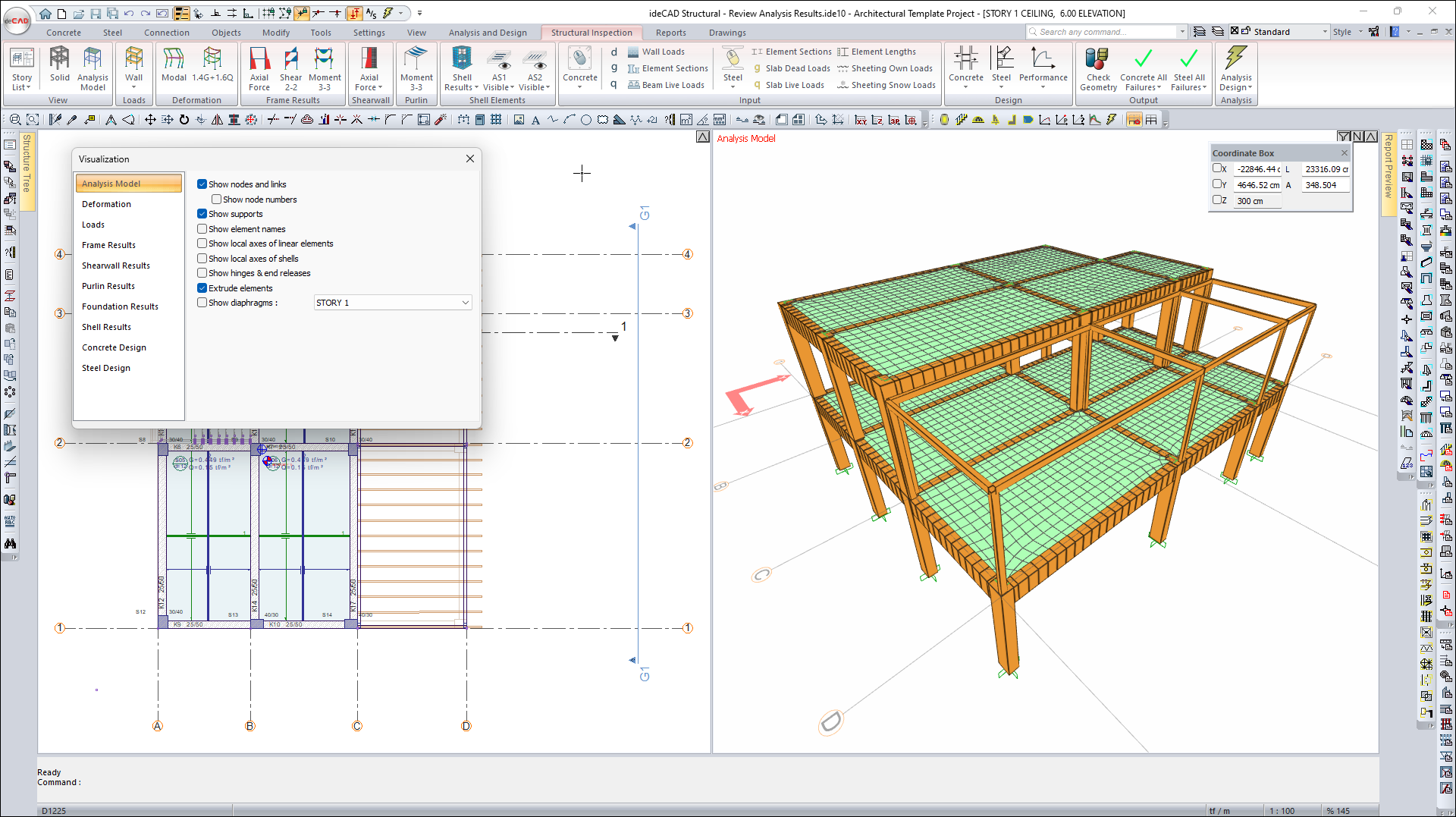
From the View heading, click the Analysis Model command.
-
In the Visualization Window, analysis model is created with beam and shell elements.
-
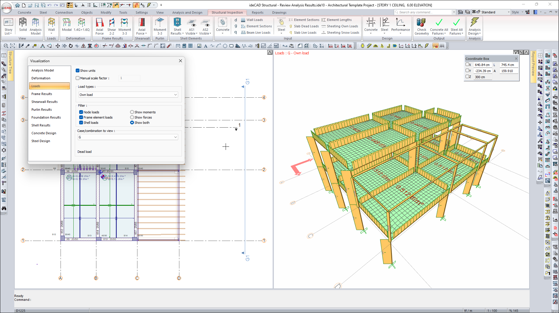
From the Visualization Dialog, click the Loads tab.
-
Open the load type list and select Own Load.
-
In the Visualization Window, examine the own load distribution of the elements.
-
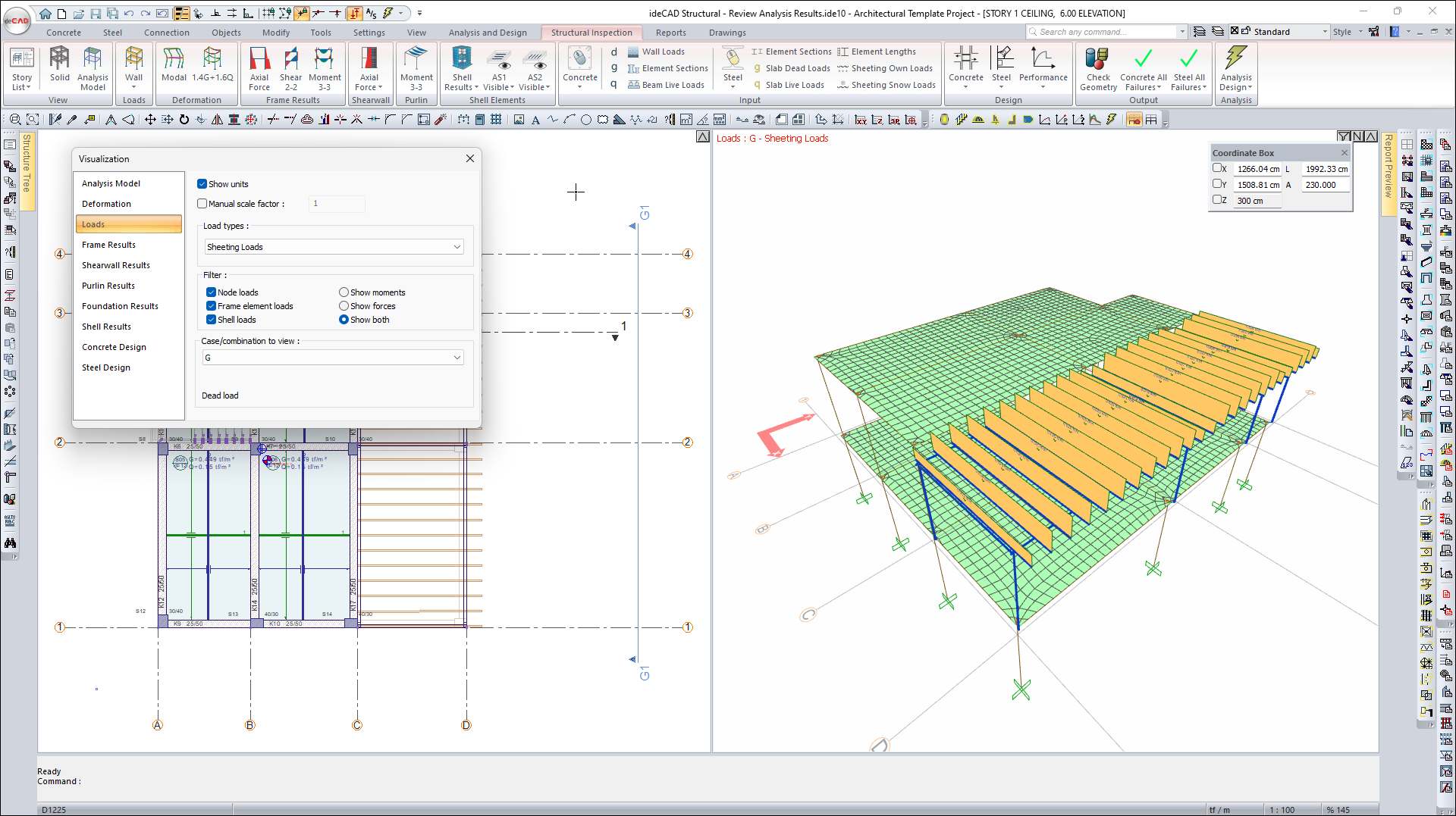
Open the load type list and select Sheeting Loads.
-
The sheeting loads acting on the steel purlins will be visible.
-
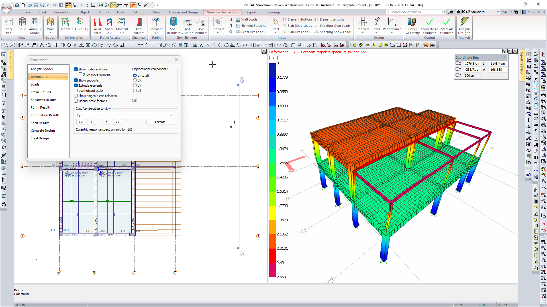
From the Visualization Dialog, click the Deformation tab.
-
Open the case/combination list and select Ey .
-
Earthquake deformation acting in the Y direction occurs in the Visualization Window.
-
From the Visualization Dialog, click the Animate command.
-
An earthquake effect animation occurs in the Y direction in the Visualization Window.
-
From the Visualization Dialog , click the Stop command to stop the animation.
-
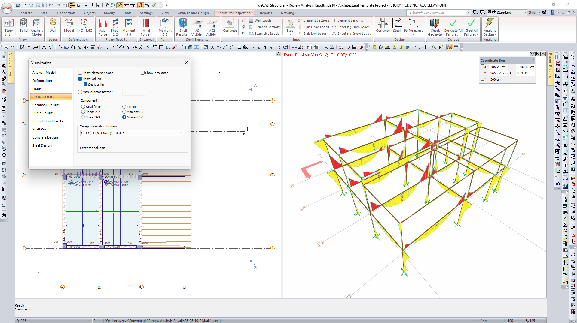
From the Visualization Dialog, click the Frame Results tab.
-
Click Moment 3-3 from the Component section.
-
Select the G'+Q'+Ex+0.3Ey+0.3Ez from the case/combination list.
-
The Moment Diagram is created in the Visualization Window .
-
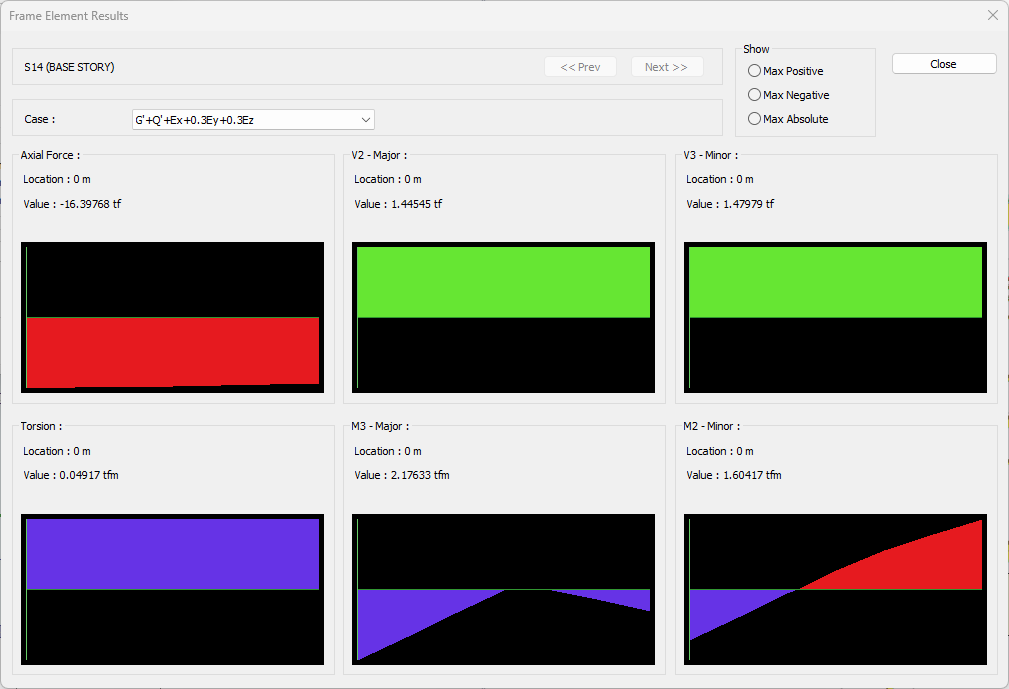
Click on the column whose result you want to see in the Visualization Window .
-
The frame element results dialog will open.
-
In the dialog that opens, all element internal force diagrams are examined.
-
Click the Close button to close the dialog.
-
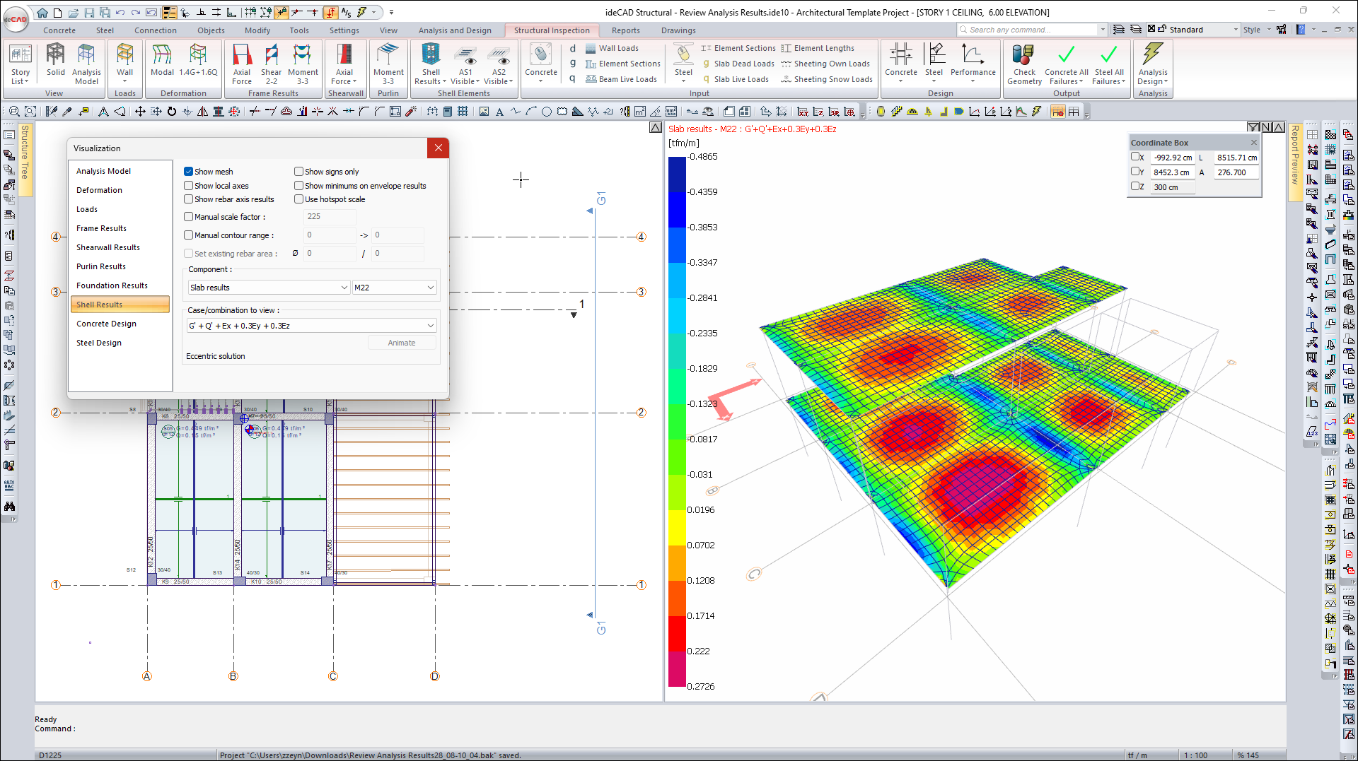
From the Visualization Dialog, click the Shell Results tab.
-
Select Slab Results and M22 from the component list .
-
In the Visualization Window, Shell finite element stresses occur.
-
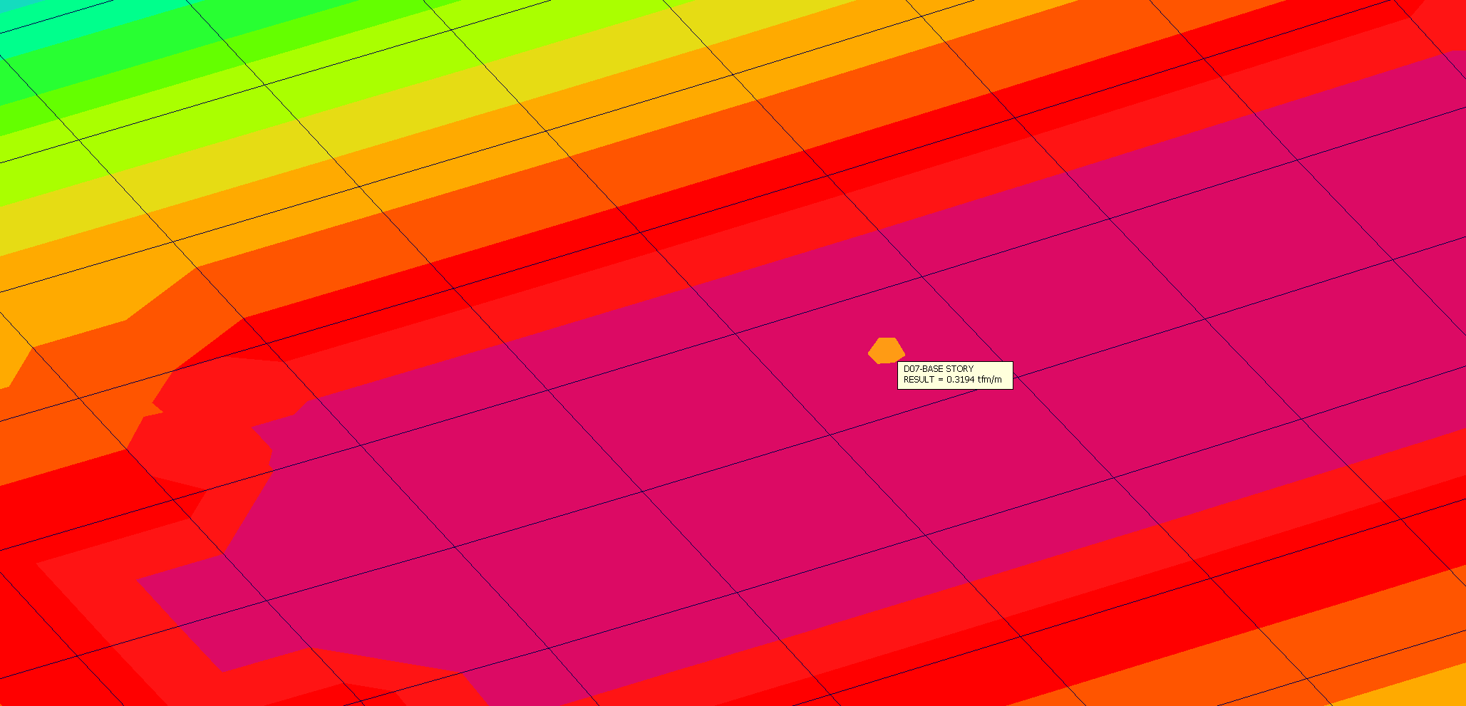
Zoom in on a slab in the Visualization Window.
-
Hover mouse over finite elements.
-
The M22 result will appear at the mouse point.
Follow the steps of the video below.
Next Tutorial