
-
Nonlinear deformations are automatically determined where confined and unwrapped concrete material model will be used.
-
Considering the concrete class determined by the user, the wrapped and unwrapped concrete material models are automatically determined as shown in Figure 5A.1.
-
The increase in tensile strength caused by the effect of the winding is automatically calculated according to the condition of the transverse and longitudinal reinforcement in the element.
Download ideCAD for Performance Based Design
ICONS
A s = Longitudinal reinforcement area
a i = Distance between the axes of the vertical reinforcement around the section
b o = Cross-section size between the axes of the stirrupssurrounding thecore concrete
E c = Elasticity module of concrete
f c = Concrete compressive stress in confined concrete
f cc = Confined concrete strength
f ck = Characteristic compressive strength of concrete
f co = Compressive strength of unconfined concrete
f e = Effective wrapping pressure
f s = Stress in reinforcing steel
f sy = Yield strength of reinforcement steel
f su = Tensile strength of reinforcing steel
f yw = Yield strength of transverse reinforcement
h o = Size of cross section between the axes of stirrupssurroundingcore concrete
k e = Coiling Efficiency Coefficient
s = Transverse reinforcement range
ρ s =Volumetric proportion of the total transverse reinforcement (rectangular in cross-section ρ s = ρ x + ρ y )
ρ x , ρ y = transverse reinforcement volume fraction in the appropriate direction
ε c = concrete compressive unit deformation of
ε c = deformation maximum pressure units in the confined concrete of
In Annex 5A.1 of TBDY Section, stress strain relations of confined and unwrapped concrete models are explained and shown in Figure 5A.1 .
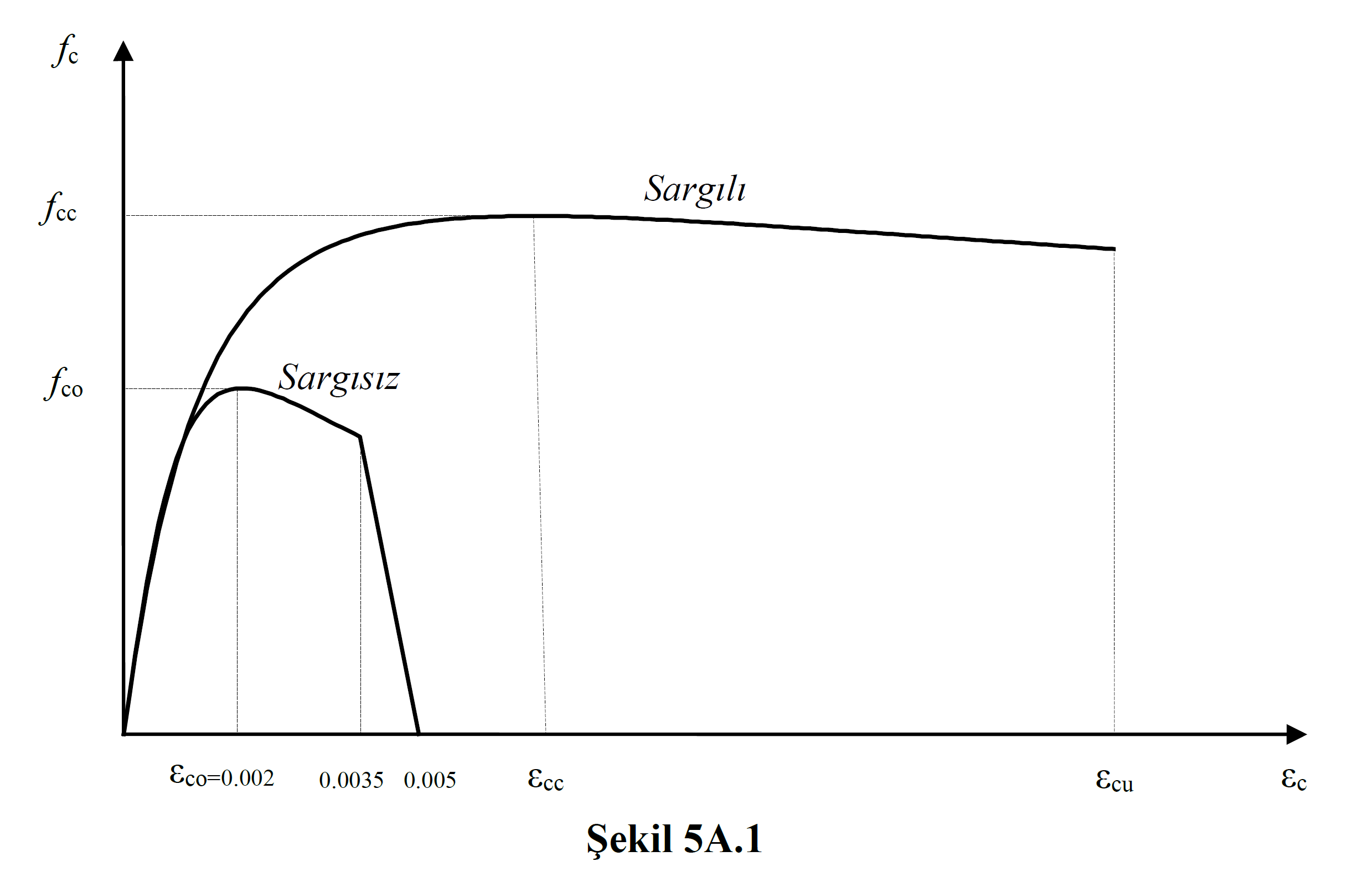
The graphs above are obtained by the equation in Equation (5A.1) .

Here f c refers to the compressive stress of concrete and is the values on the vertical axis of the graph. f cc refers to the compressive strength of confined concrete, f co refers to the compressive strength of unconfined concrete. The relation between these two is defined in Equation (5A.2) .

In this equation, f e represents the effective winding pressure. If the winding effect is not taken into account, the value of f e will be zero and λ c = 1. Then f cc = f code will be Eq. (5A.1) wherein correlation raw edge concrete will become compressive stress equation and Figure 5A.1 as depicted in raw edge concrete graph will appear.
In order to take the effect of the winding into account, the effective value of the winding pressure f e is calculated with Equation (5A.3) .

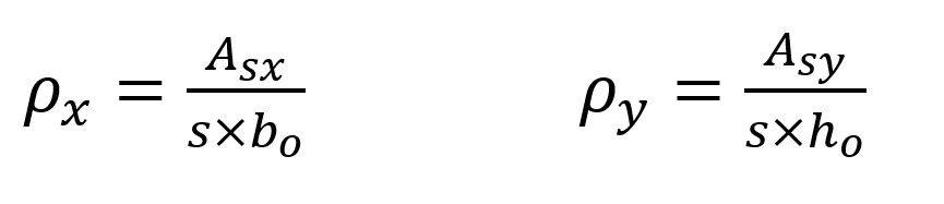
In this equation, f yw is the transverse reinforcement yield strength, ρ x and ρ y is the volumetric ratio of transverse reinforcement in the (X) and (Y) directions , respectively, and is calculated as shown below. A sx and A sy show the transverse reinforcement areas in (X) and (Y) directions, s the transverse reinforcement spacing, and b o the section size between the axes of the stirrups surrounding the core concrete.
The winding efficiency coefficient, k e value is calculated by Equation (5A.4) .

Here, a i shows the distance between the axes of the longitudinal reinforcements around the section, b o and h o the section dimensions between the axes of the stirrups surrounding the core concrete, s is the spacing between the axes of the stirrups in the longitudinal direction, and A s indicates the longitudinal reinforcement area.
After the concrete compressive stress f c is found for confined concrete and unconfined concrete, the x and r values, which are the concrete unit deformation variables in Equation (5A.1) , are shown in Equation (5A.5) and Equation (5A.6). It is calculated with.
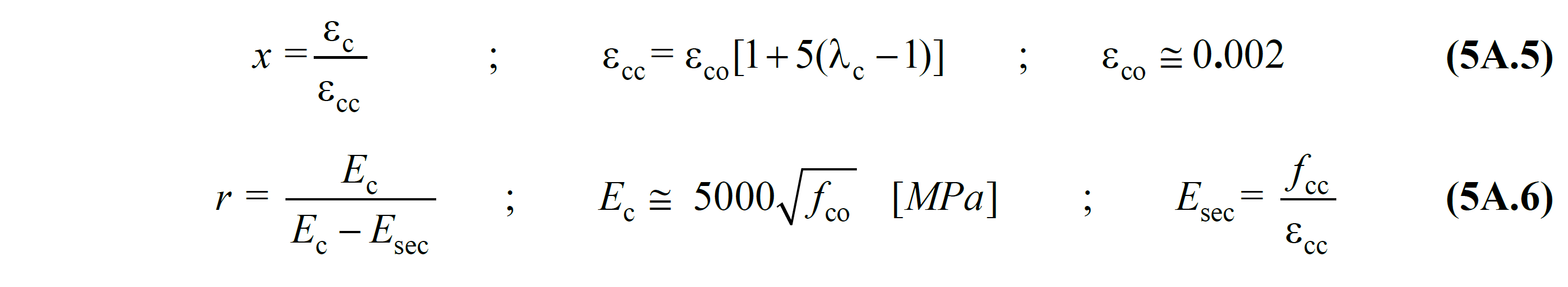
Here ε c represents the concrete unit pressure deformation and means the horizontal axis of the graph shown in Figure 5A.1 . In this case , the graph shown in Figure 5A.1 is obtained by using variables f c and ε c . ε cc confined concrete pressure unit of strain, ε co raw edge is concrete compressive deformation unit. ε cc and ε code in Eq. (5A.5) 'there is a relationship as shown. If the winding effect is not taken into account, λ c = 1 as described above . In this case ε cc = ε coand has a unit strain relation for unconfined concrete. If the winding effect is taken into account, λ c > 1 and in this case the x relation is written for confined concrete.
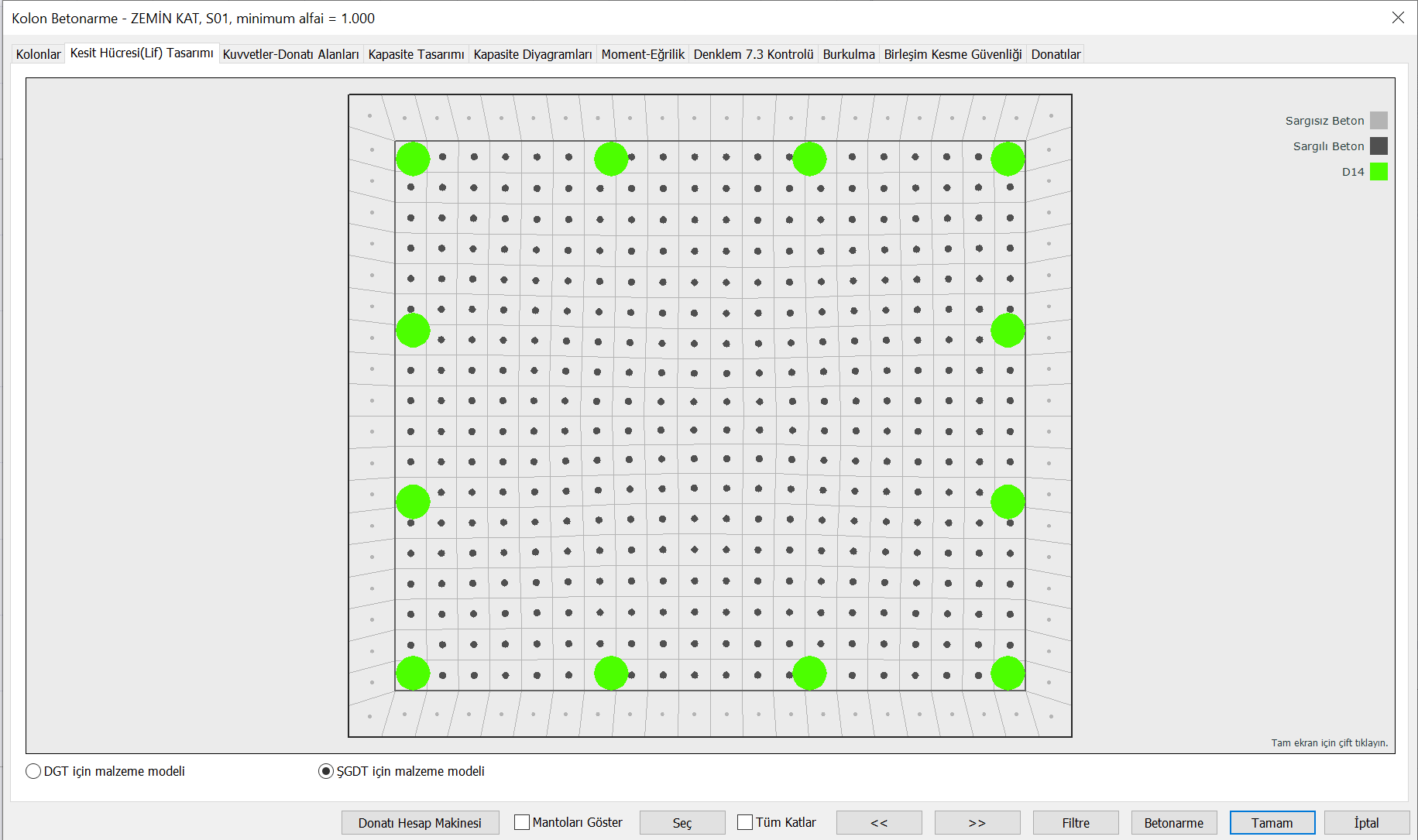
The moment-curvature relation derived to find the cross-sectional properties of plastic hinges in the Assessment and Design Based on Deformation (SSC) approach is derived according to the concrete material model described above. The following figure shows a section cell-fiber (fiber) model of an example reinforced concrete element. Here, each fiber (fiber) is defined according to the concrete material model described above. The fibers shown in dark gray are modeled as confined concrete and the fibers shown in light gray as uncoiled concrete . The ones shown in green are the fibers defined by the reinforcement material model.
When forming the concrete material model, f ck being the characteristic compressive strength of concrete, the compressive strength of uncoiled concrete, f co value depends on the concrete class. For new buildings, the concrete strength should be taken as the expected (average) strength value. In this case , it should be considered as f co = 1.3f ck and the stress strain relations for concrete should be calculated according to this value for confined and unconfined concrete. f ck is the characteristic compressive strength of concrete. In the case of evaluating existing structures, the existing material strength is used. If the knowledge level is selected as "Comprehensive", concrete strength fIf co = f ck , if the knowledge level is selected as "Limited", then f co = 0.75f ck is taken.
For example, in a concrete of C25 concrete class, f ck = 25 MPa. If this concrete class is to be used in the ŞGDT approach for an existing structure and the knowledge level is selected as "comprehensive", the concrete compressive strength used when defining the plastic joint is f ck = f co = 25 MPa. However, if the ŞGDT approach is used in a new building, the concrete compressive strength used in defining the plastic joint is the value of f co = f ce = 1.3f ck = 32.5 MPa.
Download ideCAD for ACI 318-19
Next Topic