Symbols
D = Strength excess coefficient
hi = height of the ith storey
I = Building importance coefficient
R = Load-bearing system behavior coefficient
Sae (T) = Horizontal elastic design spectral acceleration [g]
SaR (T) = Reduced design spectral acceleration [g ]
SDS = Short period design spectral acceleration coefficient [dimensionless]
SD1 = Design spectral acceleration coefficient for a period of 1.0 seconds [dimensionless]
T = Natural vibration period [s]
TA = Horizontal elastic design acceleration spectrum corner period [s]
TB = Horizontal elastic design acceleration spectrum corner period [s]
TL = Transition period to constant displacement region in horizontal elastic design spectrum [s]
ui = For any column or curtain, Reduced displacement at the i'th floor
Δi = Displacement difference between two consecutive floors for any column or curtain
δi = Effective relative floor displacement for columns or walls on the ith floor of the building
δi, max = Effective relative storey displacement for columns or walls on the i'th floor of the building
λ = Empirical coefficient used in limiting relative storey displacements
κ = Coefficient used differently for reinforced concrete and steel structural systems
-
In both horizontal earthquake directions, the maximum value δ of the effective relative storey displacements within the storey in columns and walls on any ith storey of the building must meet the maximum conditions given in TBDY 4.9.1.3.
-
The λ coefficient mentioned in TBDY 2018 4.9.1.3 is the ratio of the elastic design spectral acceleration of DD-3 earthquake ground motion to the elastic design spectral acceleration of DD-2 earthquake ground motion for the dominant vibration period in the direction of the earthquake. The coefficient is taken as 1 for reinforced concrete buildings.
-
Monolithic model results will be used in the calculation of relative floor displacement in accordance with the structural system analysis rules with no beams.
-
Detailed information about the relative floor offset account is available at Story Drift Example .
-
For the building, without any flexible joints or connections between the load-bearing system and the walls, the allowable limit value is selected in case it is completely adjacent. According to this selection, κ = 1 is taken for reinforced concrete and the limit value is calculated as 0.008.
Calculation of Lamda Coefficient
-
Modal analysis results of the monolithic model will be used.
DD-2 default values
SDS =1.112
SD1 = 0.389
Ta = 0.2*SD1 /SDS = 0.2*0.389/1.112 =0.07
Tb = SD1 / SDS =0.389 / 1.112 =0.350
DD-3 default values
SDS=0.475
SD1=0.155
Ta = 0.2*SD1 /SDS = 0.2*0.155/0.475 =0.065
Tb = SD1 / SDS =0.155 / 0.475 =0.326
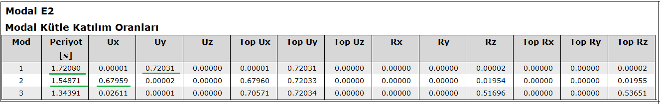
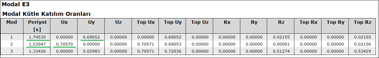
In dynamic analysis E1, E2, E3 and E4 loadings, 5 dominant vibration periods for X and Y directions are determined by reading the largest modal participation ratios compatible with the relevant direction. Out of the 4 periods determined for the X direction, the one with the highest mass participation ratio is selected. The same is done in the Y direction.
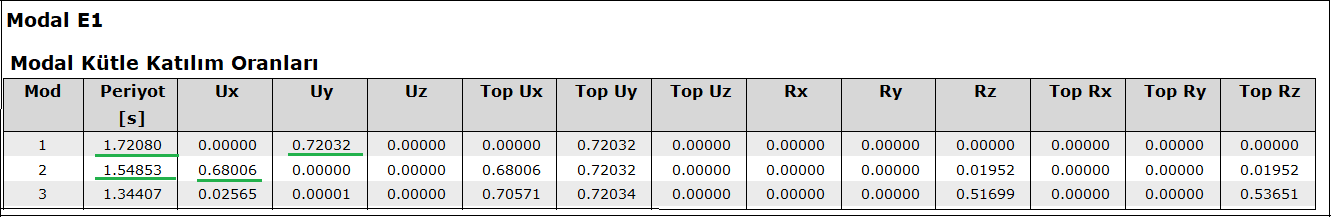
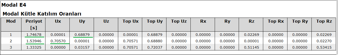
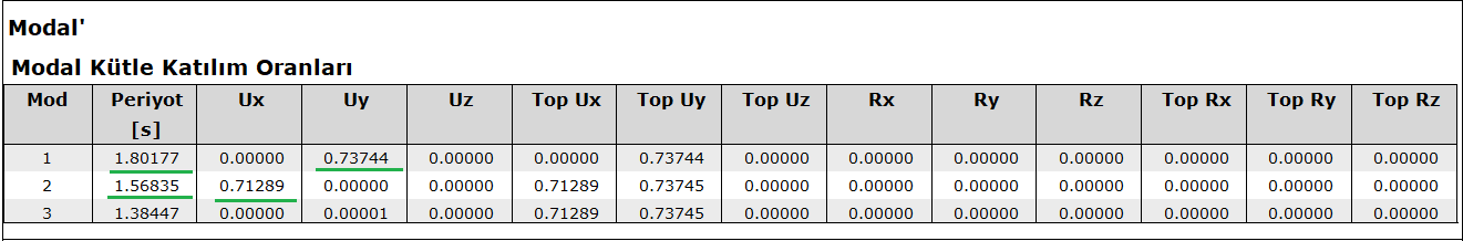
Modal 'for x direction' → T = 1.56835 sec
Modal 'for y direction' → T = 1.80177 sec
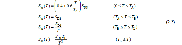
Finding the S ae (T) values
Calculation for X Direction
DD-2
For T = 1.56835 sec
Ta= 0.07 < Tb= 0.35 < T=1.56835 -> Sae(T)=SD1/T = 0.251
DD-3
For T = 1.56835 sec
Ta= 0.065 < Tb=0.326 < T=1.56835 -> Sae(T)=SD1/T= 0.100
Lamda = 0.100/ 0.251=0.3984
Calculation for Y Direction
DD-2
For T = 1.80177 sec
T=0.07> Tb=0.35< T=1.80177 -> Sae(T)=SD1/T= 0.389/ 1.80177=0.2158
DD-3
For T = 1.80177 sec
T=0.065> Tb=0.326< T=1.80177 -> Sae(T)=SD1/T= 0.155/ 1.80177=0.086
Lamda = 0.086 / 0.216=0.3984
NOTE: Since all T values in both directions are greater than T b , the lambda coefficient is actually equal to the ratio of the parameters S D1 of both ground motion levels .
-
The values calculated by the program are as follows:
-
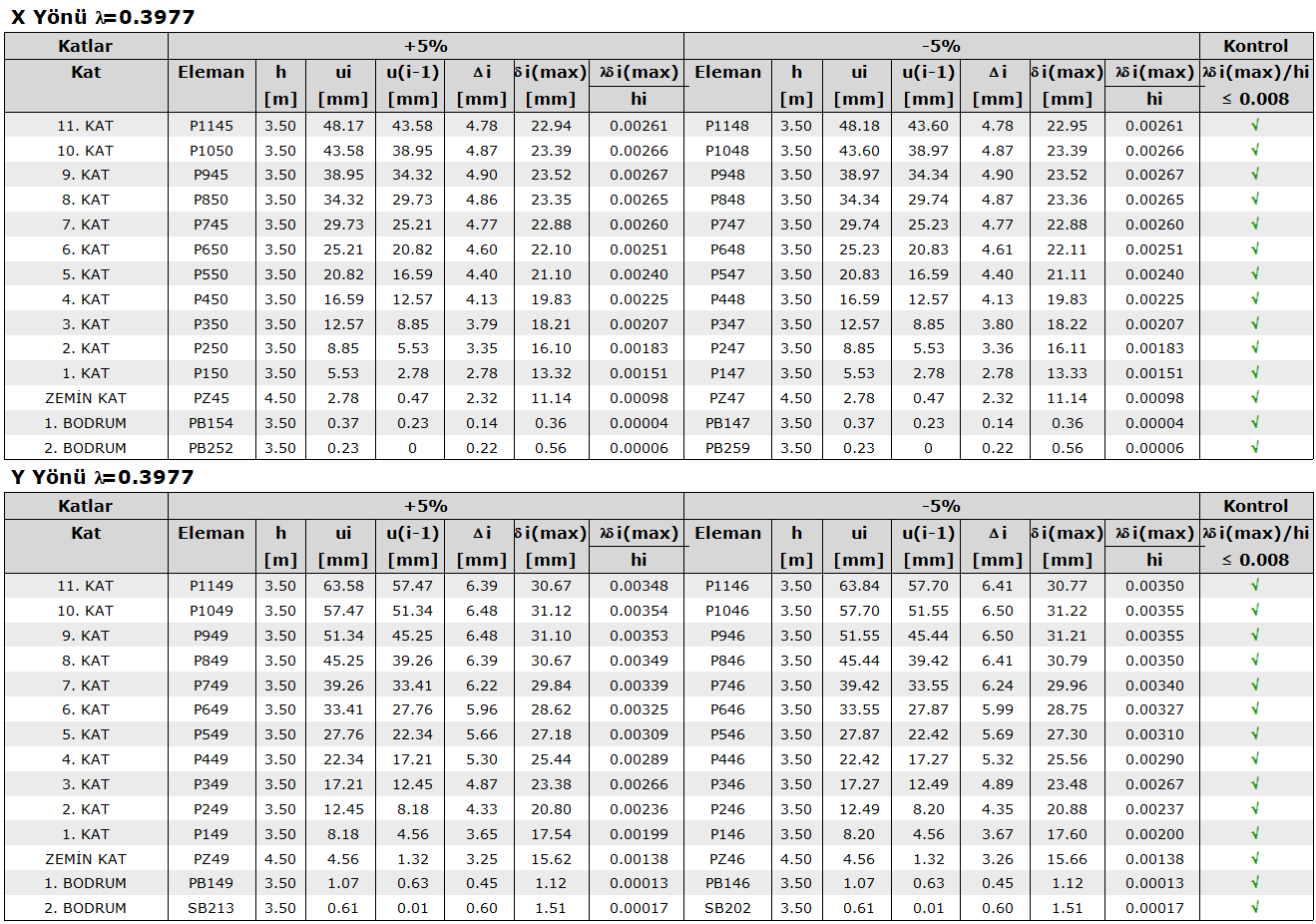
First of all, the column or curtain with the highest horizontal displacement in EX loading on each floor should be determined. For this, perspective screen - view analysis model - deformations - EX loading is selected. In each floor, the X direction displacement of the top node of the columns and walls is read and the difference between them is looked at. The largest value in the floor is used in the relative floor drift calculation.
-
This value read is the raw value. According to TBDY 2018, the raw value should be increased according to the equivalent earthquake load increase coefficient.
-
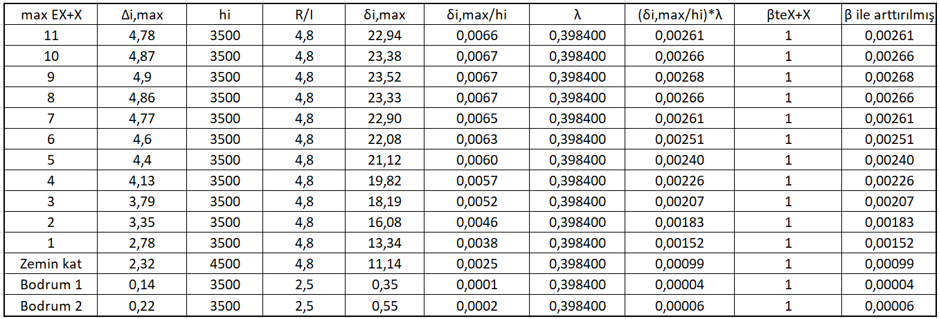
Due to the large size of the building, this action was not taken, and the relative floor drift calculation using the i value in the earthquake regulation report is summarized in the table below. The table below has only checked for X + 5%. The point to be considered here is that these results should be increased with the equivalent earthquake load increase coefficient. It is calculated as 1 in this building. Therefore, the numbers remained the same.
-
The R value used for basement floors according to TBDY 2018 is different and it was previously calculated as 2.5 for this building. For this reason, the (R / I) value given for the basement floors in the table is taken as 2.5.