
In this example, the deformations of a system consisting of 4 single-storey frame elements under distributed load will be examined. All of the bending, shear and axial deformations of the frame elements will be taken into consideration. Then bending, shear and axial deformations will be taken into consideration separately and the results will be compared.
The independent results in this example are based on Advanced Mechanics of Materials - Cook, RD and WC Young. - It is on page 244 of the 1985 book.
Eğilme, Kayma ve Eksenel_Model_1.rarEğilme, Kayma ve Eksenel_Model_2.rarEğilme, Kayma ve Eksenel_Model_3.rarEğilme, Kayma ve Eksenel_Model_4.rar
Geometric Properties and System Description
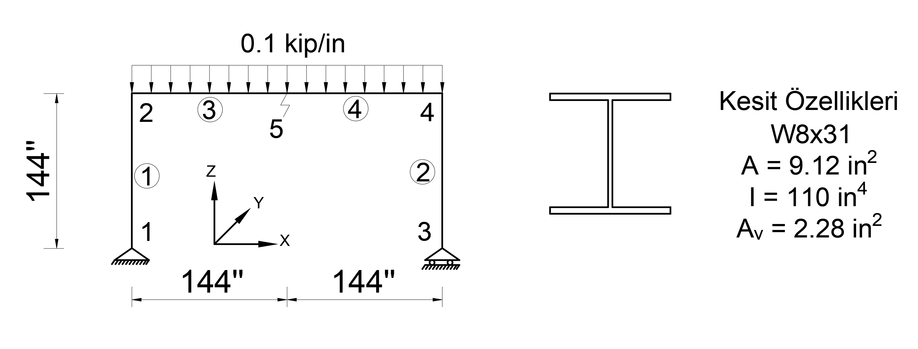
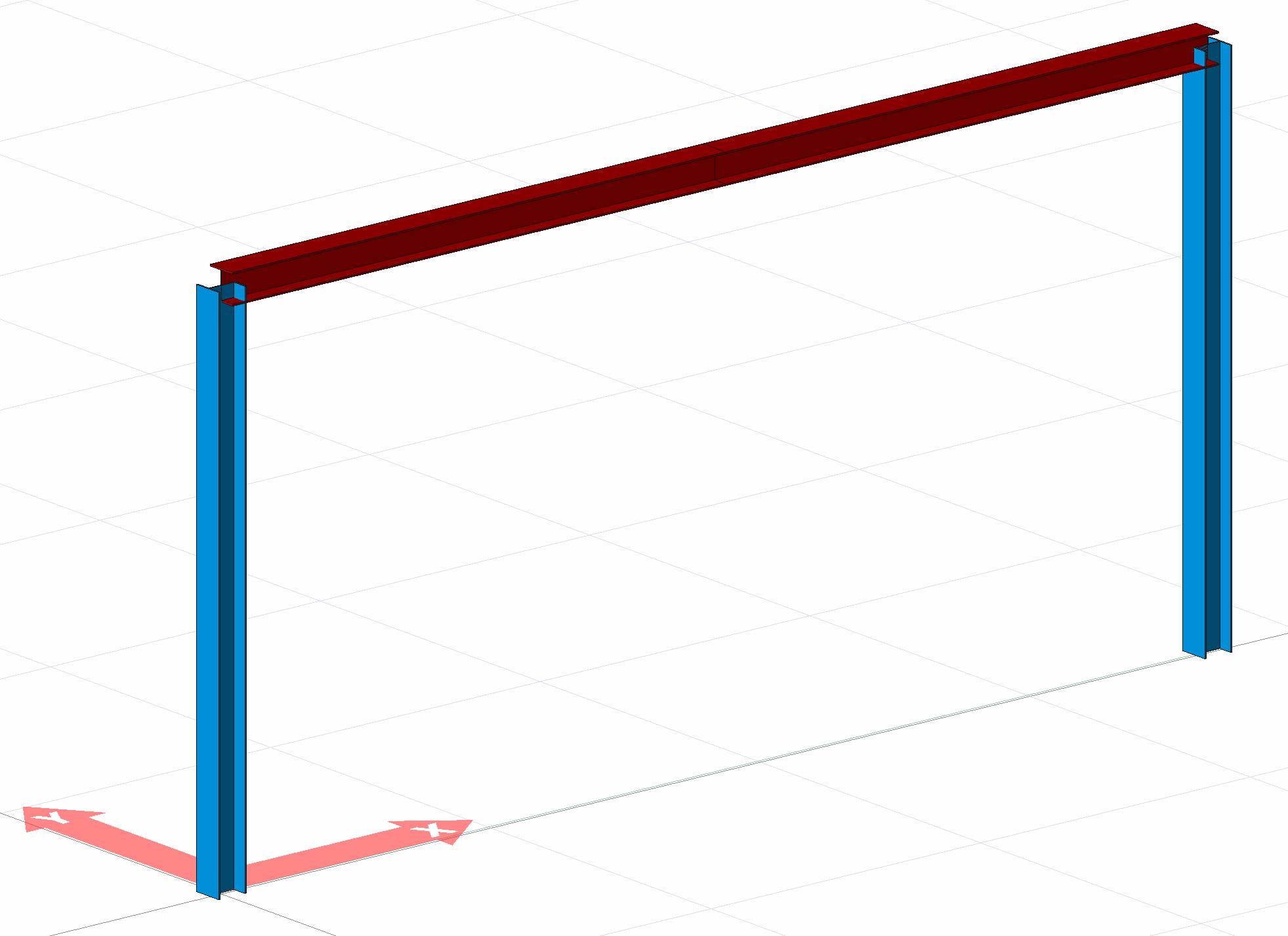
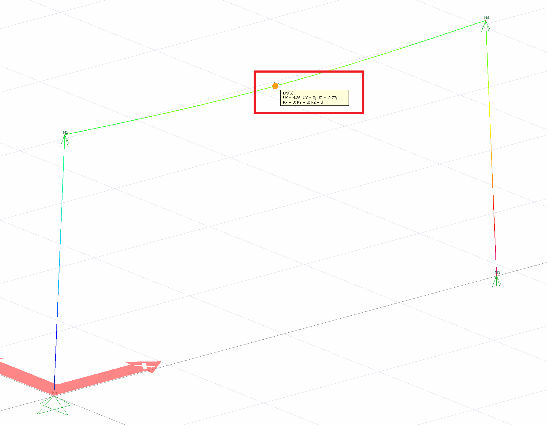
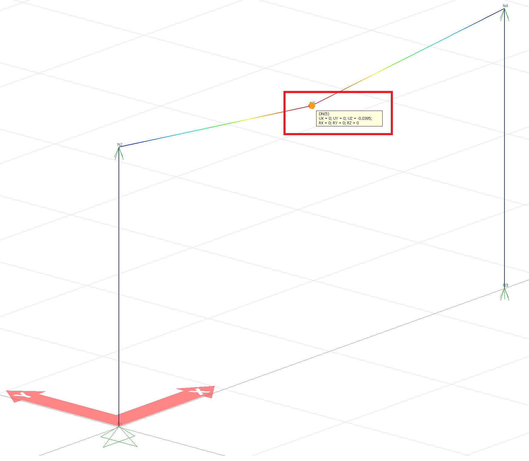
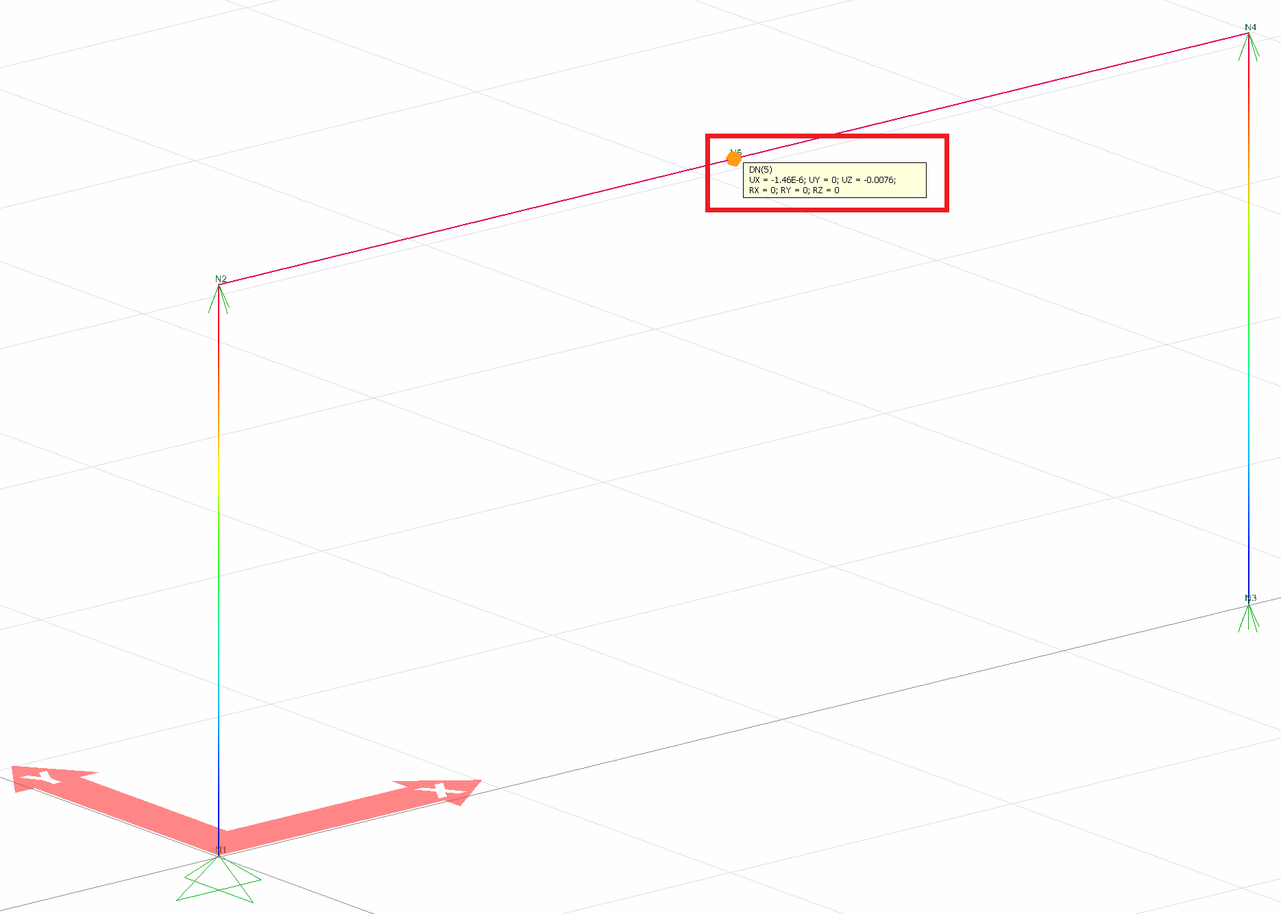
In the picture above, support conditions, joint numbers and loading status of a single storey system consisting of 4 rod elements are given. In this example, the deformation value (UZ) of joint 5 in the Z axis will be analyzed.
W8x31 section was used in the frame elements.
The area of the W8x31 section is given as A = 9.12 = 144 in 2 ,
moment of inertia I = 110 in 4 ,
shear area A v = 2.28 in 2
. The modulus of elasticity of the material used is E = 29900 k / in 2 , the poisson's ratio υ = 0.3 and the shear modulus G = 11500 k / in 2 accordingly.
Loading Cases
In this example, 4 different models were created while examining the deformation values of joint number 5. The deformations taken into consideration in these models are as follows.
-
Model 1: All of bending, shear and axial deformations
-
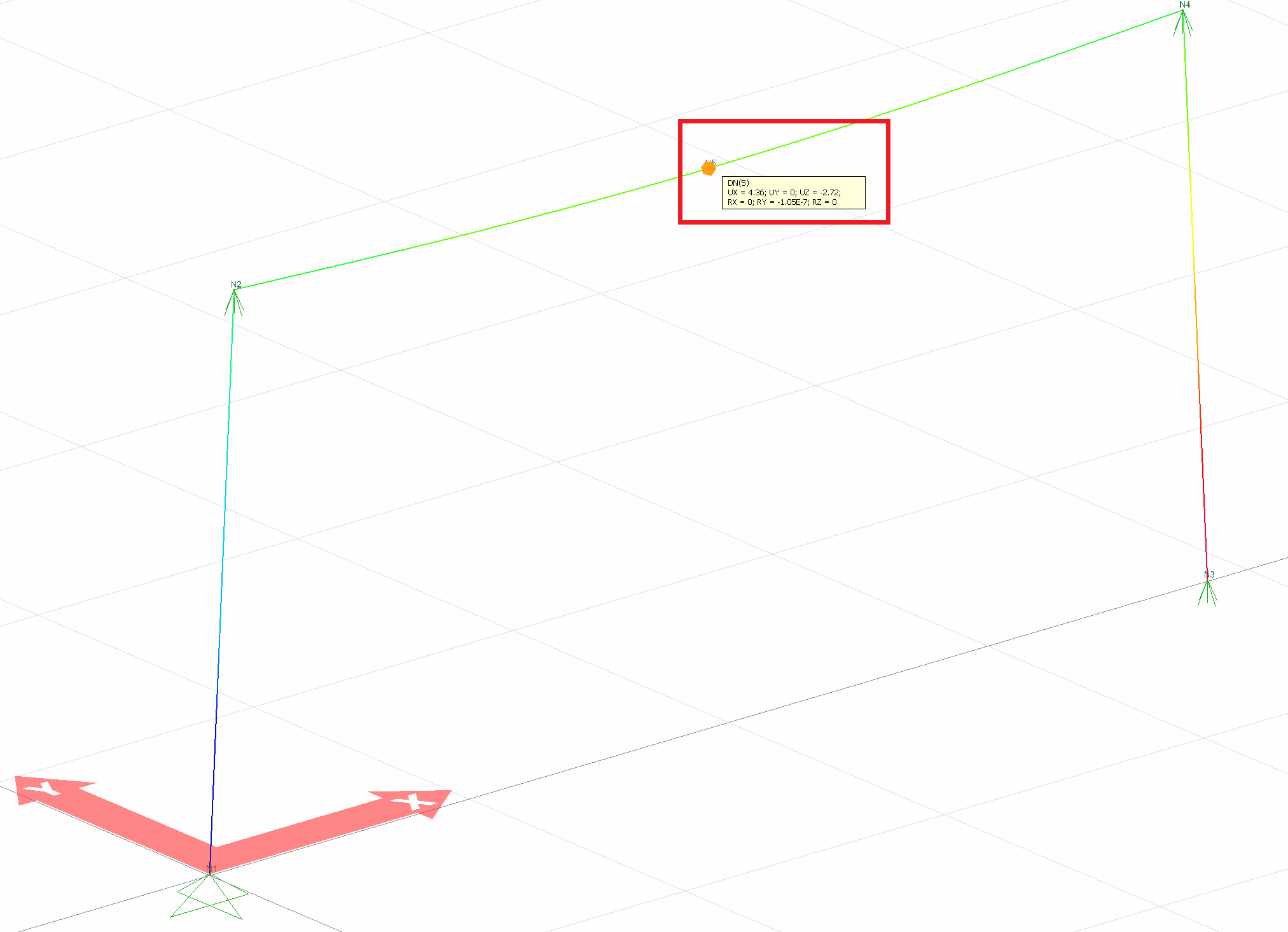
Model 2: Bending deformations only
-
Model 3: Shear deformations only
-
Model 4: Axial displacements only
|
Loading Status |
Node direction and number |
ideCAD Structural |
Manual solution |
Percentage of error |
|---|---|---|---|---|
|
Model 1
|
TO (Node # 5) (in)
|
|
|
|
|
Model 2
|
|
|
|
|
|
Model 3
|
|
|
|
|
|
Model 4
|
|
|
|
Model 1 : Considering all of the bending, shear and axial deformations, deformation in 5 DN.
Model 2 : Deformation in 5 DN considering only bending deformations.
Model 3 : Deformation in 5 DN when only shear deformations are considered.
Model 4 : Deformation in 5 DN considering axial displacements only .
Next Topic