
How does ideCAD calculate two-way slab required and design strength according to ACI 318-19?
-
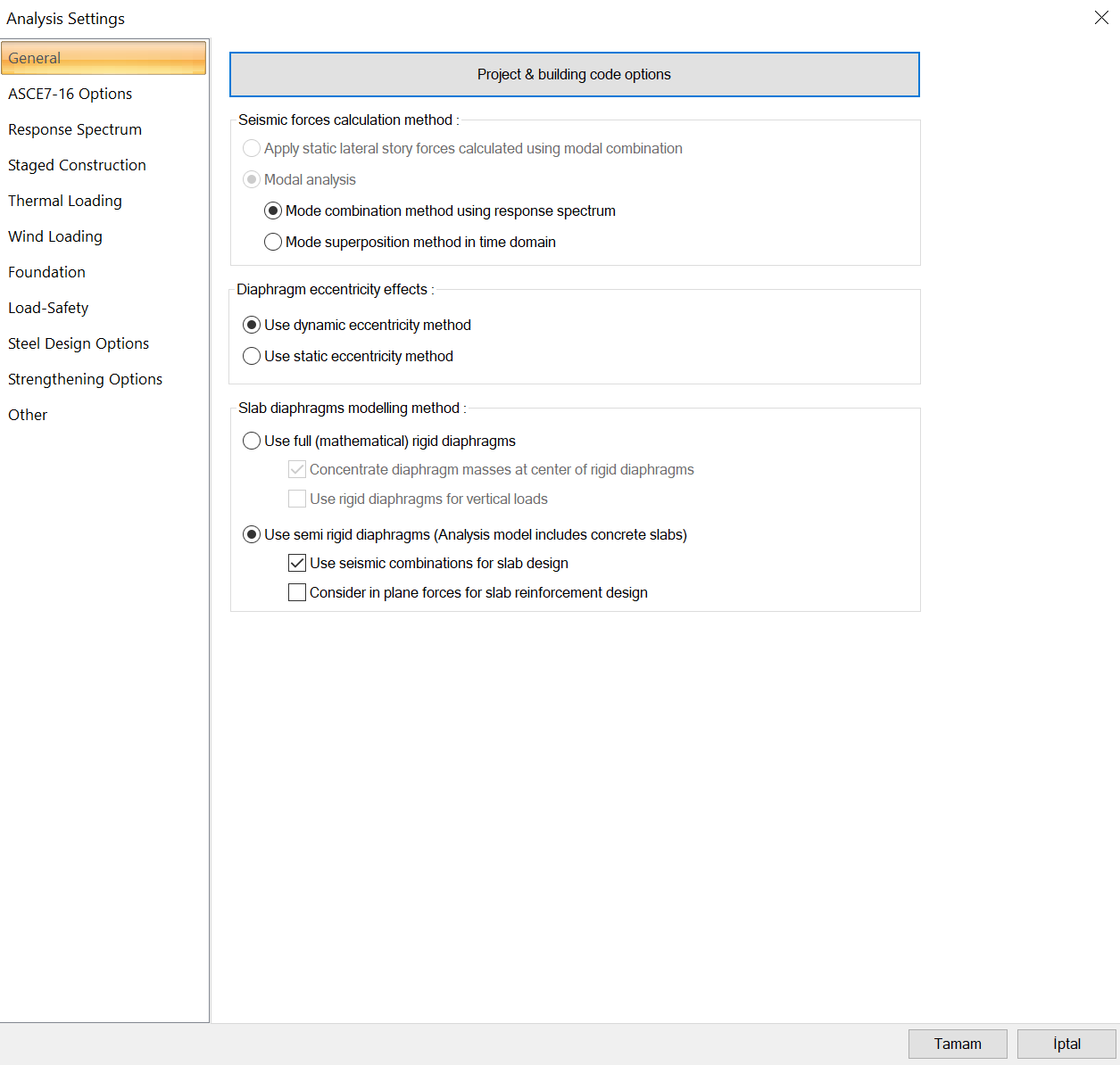
Rigid and semi-rigid diaphram conditions should be choosen by user according to irregularities defined in ASCE 7/16.
-
Analysis is done automatically according to finite element method.
-
Required strength is designed to analyse with Load Factors and Combinations per ACI 318-19 with ideCAD
-
Punching shear calculation is done automatically
Download ideCAD for ACI 318-19
Symbols
Mu = factored flexural moment at section, lb
Mn = nominal flexural strength at section, in.-lb
The required strength is designed to analyze Load Factors and Combinations per ACI 318-19 with ideCAD. The analysis is done automatically according to the finite element method. The user should choose rigid and semi-rigid diaphragm conditions according to ASCE 7/16.
Dimensions c1, c2, and ln are based on an effective support area for a slab system supported by columns or walls. A column strip is a design strip with a width on each side of a column centerline equal to the lesser of 0.25l2 and 0.25l1 according to 8.4.1.4.
Factored moment
Mu at the support is calculated at the face of support for slabs built integrally with supports.
Punching Shear Design
Punching Shear Design per ACI 318-19 with ideCAD title is concerned primarily with slab systems without beams.
Download ideCAD for ACI 318-19