Symbols
D = Strength excess coefficient
h i = height of the ith storey
I = Building importance coefficient
R = Load-bearing system behavior coefficient
u i (X) = (X) for any column or wall in the earthquake direction, reduced displacement at the i'th storey
Δ i (X) = (X) according to any column or wall earthquake, the relative displacement difference between two consecutive layers expressing reduced drift
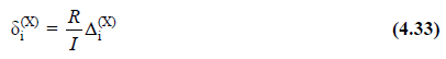
δ i (X) = (X) for the earthquake direction, the effective relative floor displacement
kolon i for the columns or walls on the i'th floor of the building , max (X) = (X) for the earthquake direction, effective relative storey drift for columns or walls on the i'th floor of the building
λ = Empirical coefficient used to limit the relative storey displacements
κ = Coefficient used differently for reinforced concrete and steel support systems in the definition of allowable relative storey displacements
4.9.1. Calculation and Limitation of Effective Relative Floor Offsets
4.9.1.1 - (X) for any column or wall earthquake direction, twice the difference between successive displacement expressing reduced relative storey drift , Δ i (X) , Eq. (4.32) to be obtained.
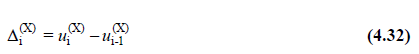
In Eq. (4.32) , for u i (X) and u i 1 ( - X) , typical (X) earthquake direction, reduced earthquake loads at the ends of any column or curtain at the ith and (i-1) floors of the building It shows the horizontal displacements calculated according to. However, in this calculation , the condition given in 4.7.3.2 and also the minimum equivalent earthquake load condition defined in Equation (4.19) will not be taken into account.
4.9.1.2 - For the typical (X) earthquake direction, the effective relative storey drift for columns or walls on the i'th storey of the building , δi (X) , will be obtained by Equation (4.33) .
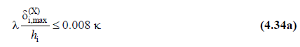
4.9.1.3 - for each seismic line, building of any ith columns or wall-floor, Eq. (4.33) calculated by δ of (X) the maximum value of the effective relative storey drifts floor δ i, max (X) , below Fulfill the conditions given in (a) or (b) .
(a) When hollow or non-voided infill walls and facade elements made of brittle material are completely adjacent to frame members, without any flexible joints or joints between them:
(b) In the event that flexible joints are made between infill walls made of brittle material and frame elements, the facade elements are connected to the outer frames by flexible connections or the infill wall element is independent from the frame:
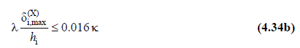
However, in this case the seam filling the wall elements, the flexible filling wall elements and flexible connection facade elements in-plane horizontal displacement capacity Eq. (4.34b) from which provides the limit of 1.4 will be documented empirically based. An example of flexible joint application for infill walls is given in ANNEX 4C .
4.9.1.4 - Eq. (4.34) 'in point λ coefficient for the characteristic periods in the earthquake direction Considering the building 02.02 defined in formula DD-3 earthquake ground motion 2.3.4.1 ' e calculated according elastic design spectral acceleration 's DD -2 is the ratio of earthquake ground motion to elastic design spectral acceleration . The coefficient in Eq. (4.34) shall be taken as = 1 for reinforced concrete buildings and = 0.5 for steel buildings.
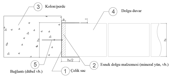
INFORMATION ATTACHMENT 4C - FLEXIBLE CONNECTION FOR FILLING WALLS
DETAIL EXAMPLE
4C.1 - Flexible joints are created between brittle infill walls and adjacent columns / curtains in order to prevent damage to the infill wall under frequently repeated DD-3 and DD-4 earthquake ground motions. These joints should be filled with a flexible material that does not prevent deformation of the wall.
4C.2 - An example detailing for flexible joints that can be applied for this purpose is given in Figure 4C.1 . The flexible joint is provided by a C-profile that is anchored to the column / curtain inner faces and the upper beam / slab lower face along the column / curtain height. This profile also prevents the out-of-plane movement of the wall during an earthquake. In the application of the detail, precautions regarding fire, heat, sound and water insulation should be taken separately.