
-
(X) for any column or wall in the earthquake direction, the reduced relative storey drift expressing the displacement difference between two consecutive floors, ∆ i (X) , is automatically obtained by Equation (4.32) .
-
In Eq. (4.32) , for u i (X) and u i-1 (X) , typical (X) earthquake direction, reduced earthquake loads at the ends of any column or curtain at the i'th and (i-1) floors of the building It shows the horizontal displacements calculated according to. However, in this calculation , the condition given in 4.7.3.2 and also the minimum equivalent earthquake load condition defined in Equation (4.19) are not taken into account automatically.
-
Typically (X) for the seismic line, for shifting the effective relative storey building ith column in solid or curtains, δ i (X) , Eq. (4.33) is obtained automatically.
-
The presence or absence of any flexible joints or connections between the frame elements of hollow or non-voided filling walls and facade elements made of brittle material is at the user's discretion.
-
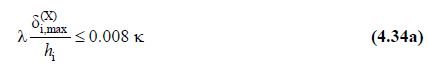
For each earthquake direction, in columns or walls on any i'th storey of the building, the maximum value etkin i (X) of effective relative storey drifts within the storey calculated by Equation. (4.33) is i, max (X) , depending on user selection. It is automatically controlled according to the conditions given in Equation (4.34a) or (4.34b) .
Symbols
|
D |
Strength excess coefficient |
|
hi |
height of the i'th floor |
|
I |
Building importance factor |
|
R |
Carrier system behavior coefficient |
|
S ac (t) |
Horizontal elastic design spectral acceleration [g] |
|
SaR(T) |
Reduced design spectral acceleration [g] |
|
SDS |
Short period design spectral acceleration coefficient [dimensionless] |
|
SD1 |
Design spectral acceleration coefficient [dimensionless] for a period of 1.0 seconds |
|
T |
Natural vibration period [s] |
|
T A |
Horizontal elastic design acceleration spectrum corner period [s] |
|
T B |
Horizontal elastic design acceleration spectrum corner period [s] |
|
T L |
Transition period [s] to constant displacement zone in horizontal elastic design spectrum |
|
u i (X) |
(X) reduced displacement at the i-th floor for any column or curtain in the earthquake direction |
|
Δi(X) |
(X) reduced relative storey drift expressing the displacement difference between two consecutive stories for any column or wall in the earthquake direction. |
|
δi(X) |
(X) effective relative storey drift for columns or walls on the i'th floor of the building for the earthquake direction |
|
δi,max(X) |
(X) effective relative storey drift for columns or walls on the i'th floor of the building for the earthquake direction |
|
λ |
Empirical coefficient used to limit the relative storey drifts |
|
K |
Coefficient used differently for reinforced concrete and steel support systems in the definition of allowed relative storey displacements |
TBDY requires the relative floor displacement control to be made for each column, not on a floor basis. In the relative floor displacement control, it is not possible to talk about the average displacement for the floor. In TBDY 4.9.1.3 , this issue was clearly stated and emphasized that "the greatest value of effective relative floor displacements" .
The Earthquake Load Reduction Coefficient determined according to Table 4.1 , Equation 4.32 used to find the horizontal displacement values of columns and walls under reduced seismic loads as to find the horizontal displacement values of columns and walls under reduced seismic loads as a result of the analysis made with R a result of the analysis made with R.
First of all, the displacements of all columns and walls in each floor are obtained for each mode. The horizontal displacement differences between two consecutive floors are then calculated using the displacements obtained for each mode and combined with an earthquake code compliant method (CQC or SRSS).
Effective relative story drift for each vertical carrier is determined by Equation 4.33. The R / I section in this equation corresponds to the calculation of the 'effective' relative floor displacement according to the unreduced earthquake loads as a result of the ' equal displacement rule ' .
The R and I values used in the account are available in the TBDY Options table in the Analysis Settings report.
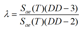
Determination of the λ Coefficient
The parameter mentioned in 4.9.1.4 is calculated by the following formula. DD-3 and DD-2 TBDY in this formula are described in Section 2.2, Earthquake Ground Motion Levels. Data for these two earthquake levels are available in the Analysis Settings Wizard Design spectra tab.
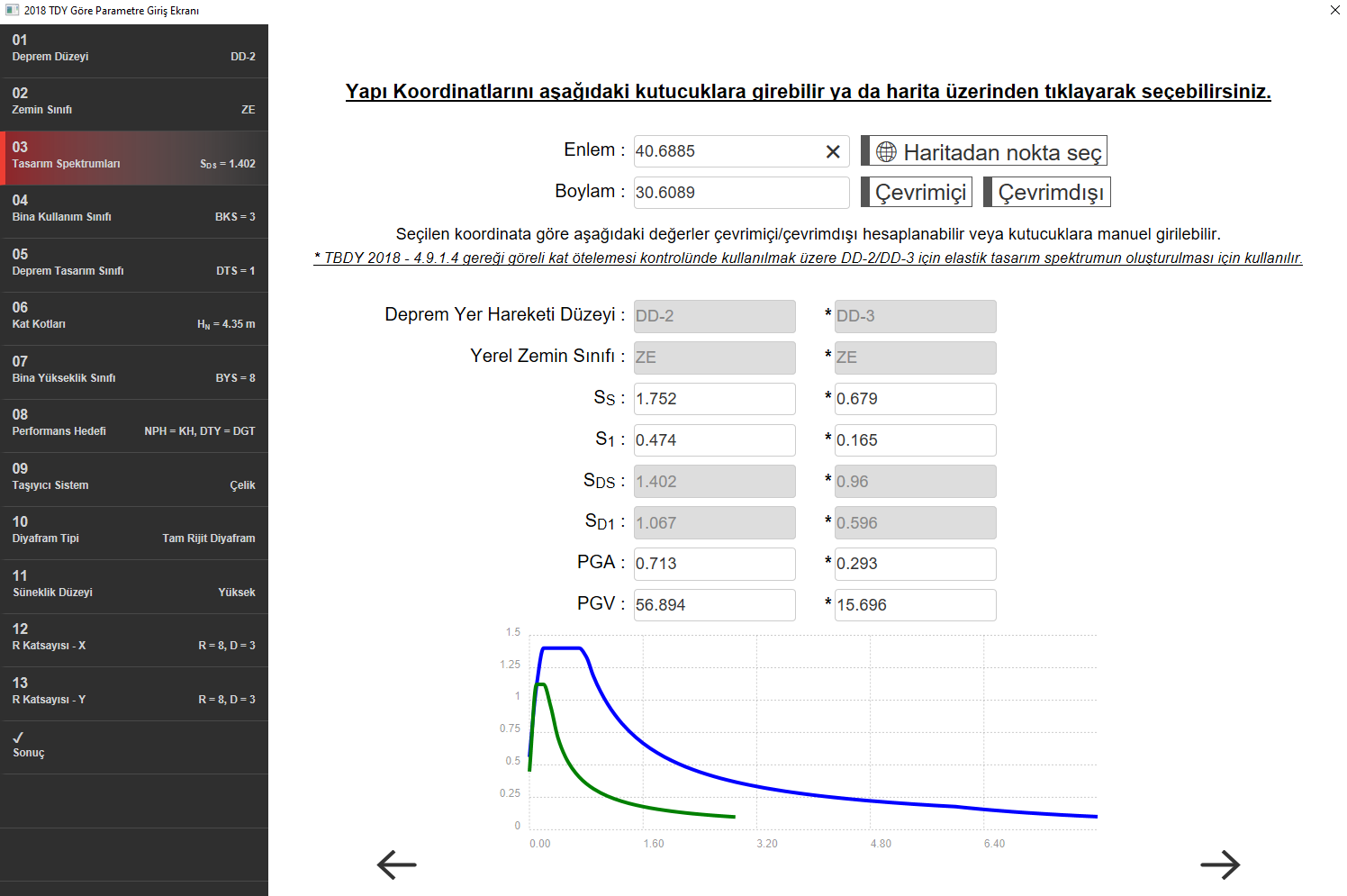
Obtaining DD-3 and DD-2 Parameters with Analysis Settings Wizard
In order to determine the elastic design spectra of DD-2 and DD-3, the relevant section should be filled in in accordance with the AFAD data. When online and offline options are used, the program automatically fills the relevant parameters according to the latitude and longitude entered. One of the online or offline options should be used after the latitude and longitude values entered. Otherwise, the set values will remain in the program interface, causing the correct earthquake load and λ coefficient to be calculated.
2.3.4 How is the Elastic Design spectral acceleration calculated?
Spectra are obtained for DD-3 and DD-2 in accordance with TBDY 2.3.4 . The necessary relations for the calculation are given in Equations 2.2 and 2.3 , respectively .
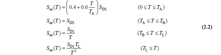
The transition period to the constant displacement zone will be taken as T L = 6 s.
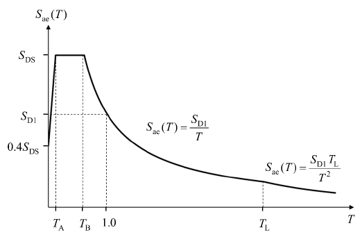
Figure 2.1
-
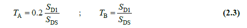
The values of S ds and S D1 given in the table under the DD-2 heading from the analysis settings wizard on the program interface above are replaced in Equation 2.3 and the corner periods T a and T b are determined. T L = 6 s value of the spectrum is given in the regulation. First of all, these 3 periods are calculated.
-
Starting from T = 0, T values are written at intervals of 0.05 up to 8 s for a suitable approximation.
-
In the function given in Equation 2.2 for the interval 0≤T aralığıT a, S DS and T a have been determined above. Using these values, the corresponding S ae (T), elastic spectral acceleration values are determined against the relevant periods .
-
For T a ≤T≤T b , the plateau part of the curve is obtained using S ae (T) = S DS .
-
For the interval T B ≤T≤T L , S ae (T) is determined by the function given in Equation 2.2 such that T L = 6 s .
-
For T L ≤T, S ae (T) is determined by using the lowest function given in Equation 2.2 . This process is terminated at T = 8s.
-
The curve in Figure 2.1 is drawn using the obtained T and S ae (T) values .
-
Steps (1-7) are applied within the earthquake level DD-3 and two curves are obtained.
-
Dynamic analysis report is received. If the dynamic eccentricity method is selected in the analysis settings, general settings tab, 4 dynamic analyzes will be made for the superstructure in the program. Of these, E1-E2 x direction is '+' and '-' is 5% eccentricity, E3-E4 is '+' and '-' is 5%. The four modal analysis results for the X and Y direction should be viewed as follows, and the unfavorable one should be selected.
-
In the dynamic analysis report, Modal Mass Participation Ratios table is displayed. The rates given under ux and uy columns in the table are only the mass participation rates for the respective mode .
-
From the table, first determine the highest mass participation rate under the ux column and read the period (T) value on the left in the same row. As a result of this process, 4 x-direction dominant vibration periods are determined. Among these periods, the one with the largest mass participation rate is selected . The same process is carried out within compliance. Thus, the relevant direction dominant vibration periods to be used in lambda calculation for the X and Y directions are determined.
-
The determined X direction period is placed in the two curves previously created and the corresponding S ae (T) values are determined. The following equation is applied to determine the λ coefficient. The same operation is performed in the Y direction.
At the end of this process, lambda coefficients are determined separately for X and Y directions.
Determination of Effective Relative Floor Displacement Limit Value
-
According to 4.9.1.4 , the coefficient of will be taken as = 1 for reinforced concrete buildings and = 0.5 for steel buildings. In the Analysis Settings report - TBDY Options table, the appropriate κ coefficient for reinforced concrete or steel is used in accordance with the selection made in the building system subtitle.
-
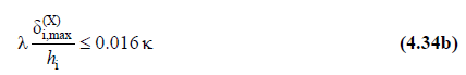
In the Analysis Settings report - TBDY Options table , the equation to be used is determined according to the selection 4.9.1.3a and 4.9.1.3b in the heading 'Connection of infill walls made of brittle material or facade elements to frame elements' . 4.9.1.3 A selection of equations to 4:34, 4.9.1.3b in the selection equation 4.34b used.
-
The h i used in Equation 4.34a and 4.34b refers to the height of the relevant floor, it is read from the program as column / curtain height.
-
All parameters of Equation 4.34 are put in place and comparison is made.
Next Topic