How does ideCAD calculate the punching shear required and design strength according to ACI 318-19?
-
Slab punching shear is checked automatically in accordance with ACI 318 - Chapter 8.
-
Punching shear reinforcement is defined by user.
Download ideCAD for ACI 318-19
Notation
Ag = gross area of the concrete section, in2
As = area of non prestressed longitudinal tension reinforcement, in2
bo = perimeter of critical section for two-way shear in slabs and footings, in.
bslab = effective slab width, in.
b1 = dimension of the critical section bo measured in the direction of the span for which moments are determined, in.
b2 = dimension of the critical section bo measured in the direction perpendicular to b1, in.
d = distance from extreme compression fiber to centroid of longitudinal tension reinforcement, in.
Ec = modulus of elasticity of concrete, psi
Es = modulus of elasticity of reinforcement, psi
√fc‘ = square root of specified compressive strength of concrete, psi
fc' = specified compressive strength of concrete, psi
fy = specified yield strength for nonprestressed reinforcement, psi
Jc = property of assumed critical section analogous to polar moment of inertia
Msc = factored slab moment that is resisted by the column at a joint, in.-lb
vc = stress corresponding to nominal two-way shear strength provided by concrete, psi
vuv = factored shear stress on the slab critical section for two-way action, from the controlling load combination, without moment transfer, psi
αs = constant used to calculate Vc in slabs and footings
ϕ = strength reduction factor
λ = modification factor to reflect the reduced mechanical properties of lightweight concrete relative to normalweight concrete of the same compressive strength
λs = factor used to modify shear strength based on the effects of member depth, commonly referred to as the size effect factor
εt = net tensile strain in extreme layer of longitudinal tension reinforcement at nominal strength, excluding strains due to effective prestress, creep, shrinkage, and temperature
εty = value of net tensile strain in the extreme layer of longitudinal tension reinforcement used to define a compression-controlled section
γf = factor used to determine the fraction of Msc transferred by slab flexure at slab-column connections
γv = factor used to determine the fraction of Msc transferred by eccentricity of shear at slab-column connections
Download ideCAD for punching Shear Design per ACI 318-19
Factored Slab Moment Resisted by the Columns
According to ACI 8.4.2.2.1, if gravity, wind, earthquake, or other loads cause a moment at the slab-column joint, a fraction of Msc , the factored slab moment resisted by the column at a joint, should be transferred by flexure in accordance with ACI 8.4.2.2.2 through ACI 8.4.2.2.5.
According to ACI 8.4.2.2.2, the fraction of unbalanced factored slab moment resisted by the column, γfMsc , is assumed to be transferred by flexure. γf is calculated in accordance with ACI Eq.(8.4.2.2.2);
'%3e%3cg transform='translate(167%2c0)'%3e%3cg transform='translate(-13%2c0)'%3e%3cg transform='translate(0%2c634)'%3e%3cuse xlink:href='%23MJMATHI-3B3' x='0' y='0'%3e%3c/use%3e%3cuse transform='scale(0.707)' xlink:href='%23MJMATHI-66' x='733' y='-219'%3e%3c/use%3e%3cuse xlink:href='%23MJMAIN-3D' x='1285' y='0'%3e%3c/use%3e%3cg transform='translate(2064%2c0)'%3e%3cg transform='translate(397%2c0)'%3e%3crect stroke='none' width='4219' height='60' x='0' y='220'%3e%3c/rect%3e%3cuse transform='scale(0.707)' xlink:href='%23MJMAIN-31' x='2733' y='602'%3e%3c/use%3e%3cg transform='translate(60%2c-991)'%3e%3cuse transform='scale(0.707)' xlink:href='%23MJMAIN-31' x='0' y='0'%3e%3c/use%3e%3cuse transform='scale(0.707)' xlink:href='%23MJMAIN-2B' x='500' y='0'%3e%3c/use%3e%3cuse transform='scale(0.707)' xlink:href='%23MJMAIN-28' x='1279' y='0'%3e%3c/use%3e%3cuse transform='scale(0.707)' xlink:href='%23MJMAIN-32' x='1668' y='0'%3e%3c/use%3e%3cuse transform='scale(0.707)' xlink:href='%23MJMAIN-2F' x='2169' y='0'%3e%3c/use%3e%3cuse transform='scale(0.707)' xlink:href='%23MJMAIN-33' x='2669' y='0'%3e%3c/use%3e%3cuse transform='scale(0.707)' xlink:href='%23MJMAIN-29' x='3170' y='0'%3e%3c/use%3e%3cg transform='translate(2516%2c0)'%3e%3cuse transform='scale(0.707)' xlink:href='%23MJSZ3-221A' x='0' y='-6'%3e%3c/use%3e%3crect stroke='none' width='875' height='42' x='707' y='979'%3e%3c/rect%3e%3cg transform='translate(707%2c0)'%3e%3cg transform='translate(120%2c0)'%3e%3crect stroke='none' width='635' height='60' x='0' y='146'%3e%3c/rect%3e%3cg transform='translate(60%2c513)'%3e%3cuse transform='scale(0.5)' xlink:href='%23MJMATHI-62' x='0' y='0'%3e%3c/use%3e%3cuse transform='scale(0.5)' xlink:href='%23MJMAIN-31' x='429' y='-323'%3e%3c/use%3e%3c/g%3e%3cg transform='translate(60%2c-347)'%3e%3cuse transform='scale(0.5)' xlink:href='%23MJMATHI-62' x='0' y='0'%3e%3c/use%3e%3cuse transform='scale(0.5)' xlink:href='%23MJMAIN-32' x='429' y='-323'%3e%3c/use%3e%3c/g%3e%3c/g%3e%3c/g%3e%3c/g%3e%3c/g%3e%3c/g%3e%3c/g%3e%3cuse xlink:href='%23MJMAIN-28' x='12912' y='0'%3e%3c/use%3e%3cg transform='translate(13301%2c0)'%3e%3cuse xlink:href='%23MJMAIN-38'%3e%3c/use%3e%3cuse xlink:href='%23MJMAIN-2E' x='500' y='0'%3e%3c/use%3e%3cuse xlink:href='%23MJMAIN-34' x='779' y='0'%3e%3c/use%3e%3cuse xlink:href='%23MJMAIN-2E' x='1279' y='0'%3e%3c/use%3e%3cuse xlink:href='%23MJMAIN-32' x='1558' y='0'%3e%3c/use%3e%3cuse xlink:href='%23MJMAIN-2E' x='2058' y='0'%3e%3c/use%3e%3cuse xlink:href='%23MJMAIN-32' x='2337' y='0'%3e%3c/use%3e%3cuse xlink:href='%23MJMAIN-2E' x='2837' y='0'%3e%3c/use%3e%3cuse xlink:href='%23MJMAIN-32' x='3116' y='0'%3e%3c/use%3e%3c/g%3e%3cuse xlink:href='%23MJMAIN-29' x='16918' y='0'%3e%3c/use%3e%3c/g%3e%3c/g%3e%3c/g%3e%3c/g%3e%3c/svg%3e)
The fraction of unbalanced moment transferred by the eccentricity of shear is taken to be γvMsc and the factor γv equals 1- γf. (γv=1- γf )
According to ACI 8.4.2.2.4, for nonprestressed slab systems without beams, where the limitations on vuv and εt in ACI Table 8.4.2.2.4 are satisfied, γf can be increased to maximum modified values provided in ACI Table 8.4.2.2.4. The calculation of two-way shear strength provided by concrete without shear reinforcement vc is explained in Two-Way Shear Strength per ACI 318-19 with ideCAD title.
|
Column location |
Span direction |
vuv |
εt |
Max. γf |
|---|---|---|---|---|
|
Corner colum |
Either direction |
|
|
1.0 |
|
Edge column |
Perpendicular to the edge |
|
|
1.0 |
|
Parallel to the edge |
|
|
|
|
|
Interior column |
Either direction |
|
|
|
'%3e%3cg transform='translate(167%2c0)'%3e%3cg transform='translate(-13%2c0)'%3e%3cg transform='translate(0%2c-47)'%3e%3cuse xlink:href='%23MJMAIN-2264' x='0' y='0'%3e%3c/use%3e%3cg transform='translate(1056%2c0)'%3e%3cuse xlink:href='%23MJMAIN-30'%3e%3c/use%3e%3cuse xlink:href='%23MJMAIN-2E' x='500' y='0'%3e%3c/use%3e%3cuse xlink:href='%23MJMAIN-35' x='779' y='0'%3e%3c/use%3e%3c/g%3e%3cuse xlink:href='%23MJMATHI-3D5' x='2335' y='0'%3e%3c/use%3e%3cg transform='translate(2932%2c0)'%3e%3cuse xlink:href='%23MJMATHI-76' x='0' y='0'%3e%3c/use%3e%3cuse transform='scale(0.707)' xlink:href='%23MJMATHI-63' x='686' y='-213'%3e%3c/use%3e%3c/g%3e%3c/g%3e%3c/g%3e%3c/g%3e%3c/g%3e%3c/svg%3e)
'%3e%3cg transform='translate(167%2c0)'%3e%3cg transform='translate(-13%2c0)'%3e%3cg transform='translate(0%2c-3)'%3e%3cuse xlink:href='%23MJMAIN-2265' x='0' y='0'%3e%3c/use%3e%3cg transform='translate(1056%2c0)'%3e%3cuse xlink:href='%23MJMATHI-3F5' x='0' y='0'%3e%3c/use%3e%3cg transform='translate(406%2c-150)'%3e%3cuse transform='scale(0.707)' xlink:href='%23MJMATHI-74' x='0' y='0'%3e%3c/use%3e%3cuse transform='scale(0.707)' xlink:href='%23MJMATHI-79' x='361' y='0'%3e%3c/use%3e%3c/g%3e%3c/g%3e%3cuse xlink:href='%23MJMAIN-2B' x='2392' y='0'%3e%3c/use%3e%3cg transform='translate(3393%2c0)'%3e%3cuse xlink:href='%23MJMAIN-30'%3e%3c/use%3e%3cuse xlink:href='%23MJMAIN-2E' x='500' y='0'%3e%3c/use%3e%3cuse xlink:href='%23MJMAIN-30' x='779' y='0'%3e%3c/use%3e%3cuse xlink:href='%23MJMAIN-30' x='1279' y='0'%3e%3c/use%3e%3cuse xlink:href='%23MJMAIN-33' x='1780' y='0'%3e%3c/use%3e%3c/g%3e%3c/g%3e%3c/g%3e%3c/g%3e%3c/g%3e%3c/svg%3e)
'%3e%3cg transform='translate(167%2c0)'%3e%3cg transform='translate(-13%2c0)'%3e%3cg transform='translate(0%2c-47)'%3e%3cuse xlink:href='%23MJMAIN-2264' x='0' y='0'%3e%3c/use%3e%3cg transform='translate(1056%2c0)'%3e%3cuse xlink:href='%23MJMAIN-30'%3e%3c/use%3e%3cuse xlink:href='%23MJMAIN-2E' x='500' y='0'%3e%3c/use%3e%3cuse xlink:href='%23MJMAIN-37' x='779' y='0'%3e%3c/use%3e%3cuse xlink:href='%23MJMAIN-35' x='1279' y='0'%3e%3c/use%3e%3c/g%3e%3cuse xlink:href='%23MJMATHI-3D5' x='2836' y='0'%3e%3c/use%3e%3cg transform='translate(3432%2c0)'%3e%3cuse xlink:href='%23MJMATHI-76' x='0' y='0'%3e%3c/use%3e%3cuse transform='scale(0.707)' xlink:href='%23MJMATHI-63' x='686' y='-213'%3e%3c/use%3e%3c/g%3e%3c/g%3e%3c/g%3e%3c/g%3e%3c/g%3e%3c/svg%3e)
'%3e%3cg transform='translate(167%2c0)'%3e%3cg transform='translate(-13%2c0)'%3e%3cg transform='translate(0%2c-47)'%3e%3cuse xlink:href='%23MJMAIN-2264' x='0' y='0'%3e%3c/use%3e%3cg transform='translate(1056%2c0)'%3e%3cuse xlink:href='%23MJMAIN-30'%3e%3c/use%3e%3cuse xlink:href='%23MJMAIN-2E' x='500' y='0'%3e%3c/use%3e%3cuse xlink:href='%23MJMAIN-34' x='779' y='0'%3e%3c/use%3e%3c/g%3e%3cuse xlink:href='%23MJMATHI-3D5' x='2335' y='0'%3e%3c/use%3e%3cg transform='translate(2932%2c0)'%3e%3cuse xlink:href='%23MJMATHI-76' x='0' y='0'%3e%3c/use%3e%3cuse transform='scale(0.707)' xlink:href='%23MJMATHI-63' x='686' y='-213'%3e%3c/use%3e%3c/g%3e%3c/g%3e%3c/g%3e%3c/g%3e%3c/g%3e%3c/svg%3e)
'%3e%3cg transform='translate(167%2c0)'%3e%3cg transform='translate(-13%2c0)'%3e%3cg transform='translate(0%2c-3)'%3e%3cuse xlink:href='%23MJMAIN-2265' x='0' y='0'%3e%3c/use%3e%3cg transform='translate(1056%2c0)'%3e%3cuse xlink:href='%23MJMATHI-3F5' x='0' y='0'%3e%3c/use%3e%3cg transform='translate(406%2c-150)'%3e%3cuse transform='scale(0.707)' xlink:href='%23MJMATHI-74' x='0' y='0'%3e%3c/use%3e%3cuse transform='scale(0.707)' xlink:href='%23MJMATHI-79' x='361' y='0'%3e%3c/use%3e%3c/g%3e%3c/g%3e%3cuse xlink:href='%23MJMAIN-2B' x='2392' y='0'%3e%3c/use%3e%3cg transform='translate(3393%2c0)'%3e%3cuse xlink:href='%23MJMAIN-30'%3e%3c/use%3e%3cuse xlink:href='%23MJMAIN-2E' x='500' y='0'%3e%3c/use%3e%3cuse xlink:href='%23MJMAIN-30' x='779' y='0'%3e%3c/use%3e%3cuse xlink:href='%23MJMAIN-30' x='1279' y='0'%3e%3c/use%3e%3cuse xlink:href='%23MJMAIN-38' x='1780' y='0'%3e%3c/use%3e%3c/g%3e%3c/g%3e%3c/g%3e%3c/g%3e%3c/g%3e%3c/svg%3e)
'%3e%3cg transform='translate(167%2c0)'%3e%3cg transform='translate(-13%2c0)'%3e%3cg transform='translate(0%2c626)'%3e%3cg transform='translate(120%2c0)'%3e%3crect stroke='none' width='4219' height='60' x='0' y='220'%3e%3c/rect%3e%3cg transform='translate(1480%2c441)'%3e%3cuse transform='scale(0.707)' xlink:href='%23MJMAIN-31'%3e%3c/use%3e%3cuse transform='scale(0.707)' xlink:href='%23MJMAIN-2E' x='500' y='0'%3e%3c/use%3e%3cuse transform='scale(0.707)' xlink:href='%23MJMAIN-32' x='779' y='0'%3e%3c/use%3e%3cuse transform='scale(0.707)' xlink:href='%23MJMAIN-35' x='1279' y='0'%3e%3c/use%3e%3c/g%3e%3cg transform='translate(60%2c-991)'%3e%3cuse transform='scale(0.707)' xlink:href='%23MJMAIN-31' x='0' y='0'%3e%3c/use%3e%3cuse transform='scale(0.707)' xlink:href='%23MJMAIN-2B' x='500' y='0'%3e%3c/use%3e%3cuse transform='scale(0.707)' xlink:href='%23MJMAIN-28' x='1279' y='0'%3e%3c/use%3e%3cuse transform='scale(0.707)' xlink:href='%23MJMAIN-32' x='1668' y='0'%3e%3c/use%3e%3cuse transform='scale(0.707)' xlink:href='%23MJMAIN-2F' x='2169' y='0'%3e%3c/use%3e%3cuse transform='scale(0.707)' xlink:href='%23MJMAIN-33' x='2669' y='0'%3e%3c/use%3e%3cuse transform='scale(0.707)' xlink:href='%23MJMAIN-29' x='3170' y='0'%3e%3c/use%3e%3cg transform='translate(2516%2c0)'%3e%3cuse transform='scale(0.707)' xlink:href='%23MJSZ3-221A' x='0' y='-6'%3e%3c/use%3e%3crect stroke='none' width='875' height='42' x='707' y='979'%3e%3c/rect%3e%3cg transform='translate(707%2c0)'%3e%3cg transform='translate(120%2c0)'%3e%3crect stroke='none' width='635' height='60' x='0' y='146'%3e%3c/rect%3e%3cg transform='translate(60%2c513)'%3e%3cuse transform='scale(0.5)' xlink:href='%23MJMATHI-62' x='0' y='0'%3e%3c/use%3e%3cuse transform='scale(0.5)' xlink:href='%23MJMAIN-31' x='429' y='-323'%3e%3c/use%3e%3c/g%3e%3cg transform='translate(60%2c-347)'%3e%3cuse transform='scale(0.5)' xlink:href='%23MJMATHI-62' x='0' y='0'%3e%3c/use%3e%3cuse transform='scale(0.5)' xlink:href='%23MJMAIN-32' x='429' y='-323'%3e%3c/use%3e%3c/g%3e%3c/g%3e%3c/g%3e%3c/g%3e%3c/g%3e%3c/g%3e%3cuse xlink:href='%23MJMAIN-2264' x='4737' y='0'%3e%3c/use%3e%3cg transform='translate(5793%2c0)'%3e%3cuse xlink:href='%23MJMAIN-31'%3e%3c/use%3e%3cuse xlink:href='%23MJMAIN-2E' x='500' y='0'%3e%3c/use%3e%3cuse xlink:href='%23MJMAIN-30' x='779' y='0'%3e%3c/use%3e%3c/g%3e%3c/g%3e%3c/g%3e%3c/g%3e%3c/g%3e%3c/svg%3e)
Critical Section
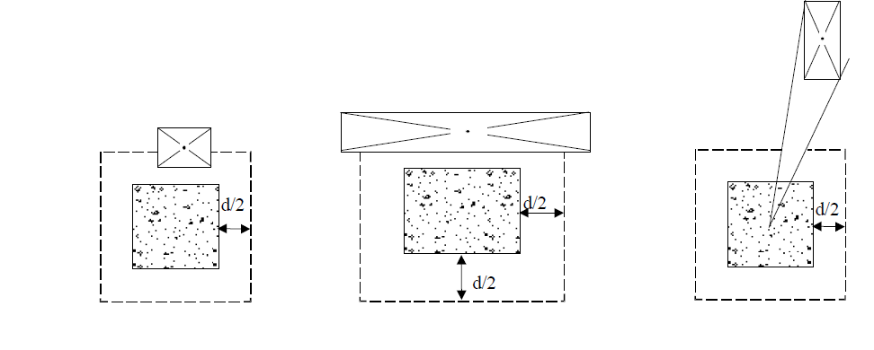
According to ACI 22.6.4.1, for two-way shear, critical sections should be located so that perimeter bo is a minimum but need not be closer than d/2 to the two cases given below;
-
Edges or corners of columns, concentrated loads, or reaction areas
-
Changes in slab or footing thickness, such as edges of capitals, drop panels, or shear caps
According to ACI 22.6.4.1.1, concentrated loads, or reaction areas, critical sections for two-way shear in accordance with ACI 22.6.4.1 (case 1 and case 2) can be defined assuming straight sides for square or rectangular columns.
According to ACI 22.6.4.1.2, critical sections for two-way shear in accordance with ACI 22.6.4.1 (case 1 and case 2) can be defined assuming a square column of equivalent area for a circular or regular polygon-shaped column.
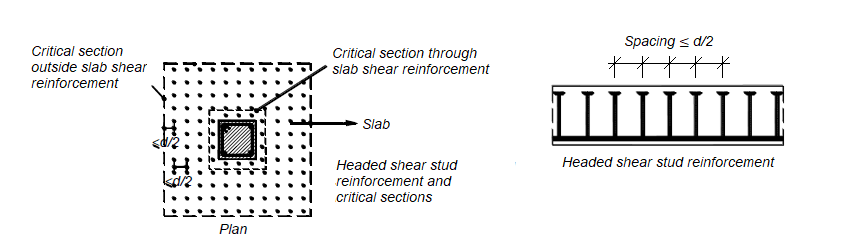
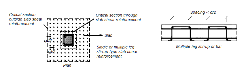
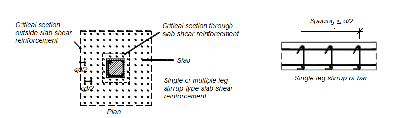
According to ACI 22.6.4.2, for two-way members with single (or multi) leg stirrup or headed stud shear reinforcement, one more critical section with perimeter bo located d/2 beyond the point where shear reinforcement is discontinued. The shape of this critical section should be a polygon selected to minimize bo.
The value of bo is shown in the figure below.
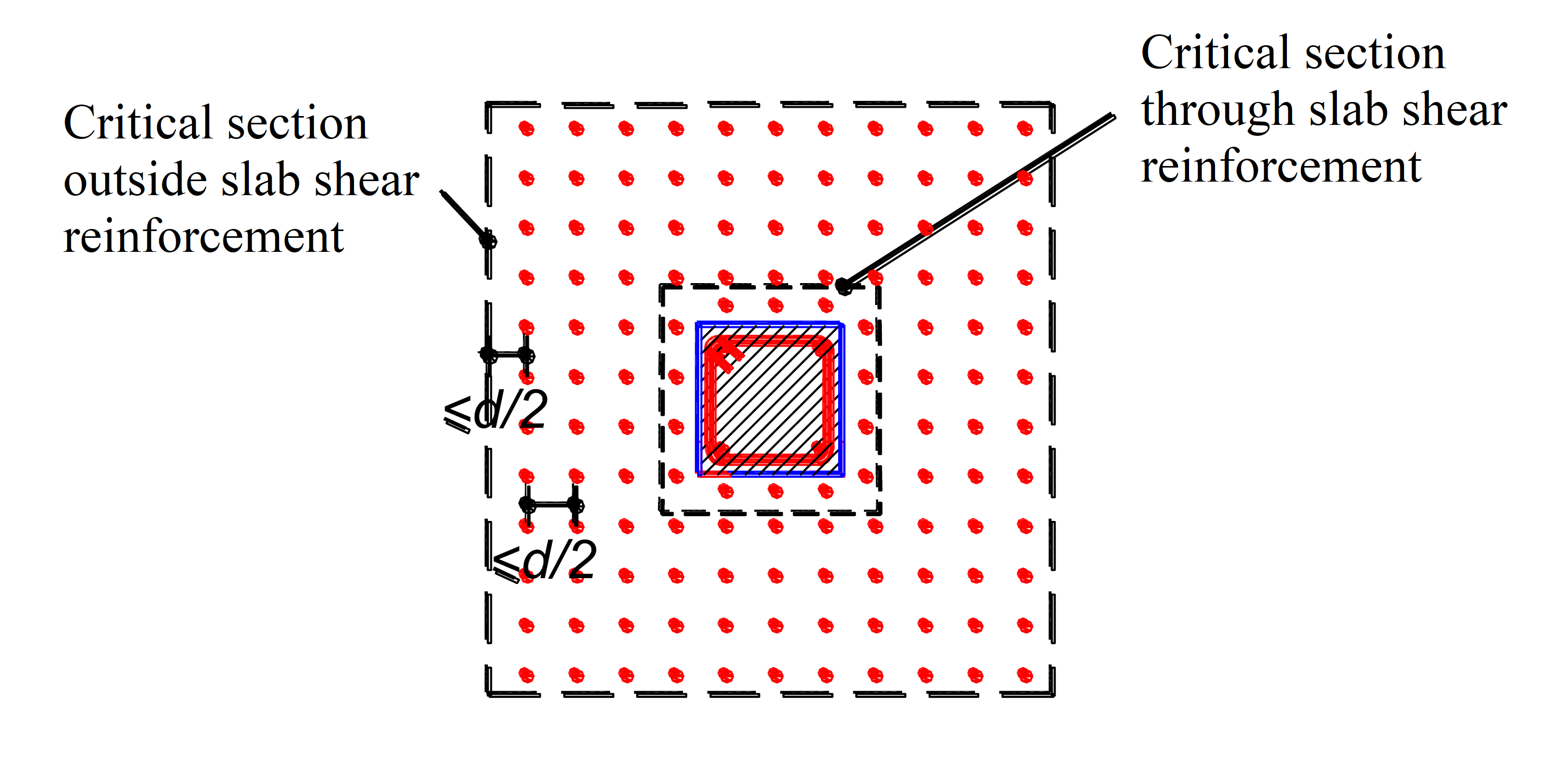
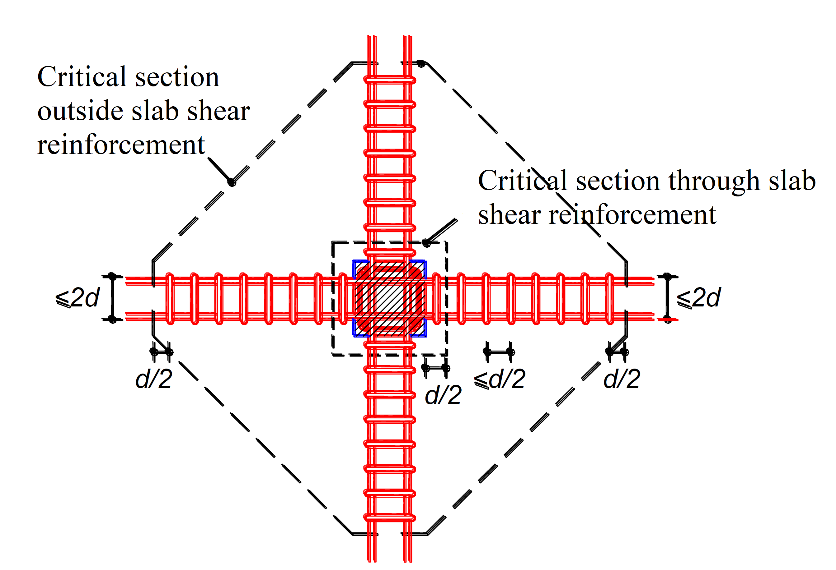
According to ACI 22.6.4.3, If there is an opening located closer than 4h from the periphery of a column, concentrated load, or reaction area, the portion of bo enclosed by straight lines projecting from the centroid of the column, concentrated load or reaction area and tangent to the boundaries of the opening should be considered ineffective.
Factored Two-way Shear Stress Due to Shear and Factored Slab Moment Resisted by the Column
According to ACI 8.4.4.2.1, for punching shear with factored slab moment resisted by the column, factored shear stress vu should be calculated at critical sections. Factored shear stress vu corresponds to combinations of vuv and γvMsc.
According to ACI 8.4.4.2.2, γvMsc is the fraction of unbalanced moment transferred by eccentricity of shear. The fraction of Msc should be applied at the centroid of the critical section. γv is taken as specified in ACI Eq. (8.4.4.2.2);
'%3e%3cg transform='translate(167%2c0)'%3e%3cg transform='translate(-13%2c0)'%3e%3cuse xlink:href='%23MJMATHI-3B3' x='0' y='0'%3e%3c/use%3e%3cuse transform='scale(0.707)' xlink:href='%23MJMATHI-76' x='733' y='-213'%3e%3c/use%3e%3cuse xlink:href='%23MJMAIN-3D' x='1239' y='0'%3e%3c/use%3e%3cuse xlink:href='%23MJMAIN-31' x='2295' y='0'%3e%3c/use%3e%3cuse xlink:href='%23MJMAIN-2212' x='3018' y='0'%3e%3c/use%3e%3cg transform='translate(4019%2c0)'%3e%3cuse xlink:href='%23MJMATHI-3B3' x='0' y='0'%3e%3c/use%3e%3cuse transform='scale(0.707)' xlink:href='%23MJMATHI-66' x='733' y='-219'%3e%3c/use%3e%3c/g%3e%3cuse xlink:href='%23MJMAIN-28' x='11138' y='0'%3e%3c/use%3e%3cg transform='translate(11527%2c0)'%3e%3cuse xlink:href='%23MJMAIN-38'%3e%3c/use%3e%3cuse xlink:href='%23MJMAIN-2E' x='500' y='0'%3e%3c/use%3e%3cuse xlink:href='%23MJMAIN-34' x='779' y='0'%3e%3c/use%3e%3cuse xlink:href='%23MJMAIN-2E' x='1279' y='0'%3e%3c/use%3e%3cuse xlink:href='%23MJMAIN-34' x='1558' y='0'%3e%3c/use%3e%3cuse xlink:href='%23MJMAIN-2E' x='2058' y='0'%3e%3c/use%3e%3cuse xlink:href='%23MJMAIN-32' x='2337' y='0'%3e%3c/use%3e%3cuse xlink:href='%23MJMAIN-2E' x='2837' y='0'%3e%3c/use%3e%3cuse xlink:href='%23MJMAIN-32' x='3116' y='0'%3e%3c/use%3e%3c/g%3e%3cuse xlink:href='%23MJMAIN-29' x='15144' y='0'%3e%3c/use%3e%3c/g%3e%3c/g%3e%3c/g%3e%3c/svg%3e)
According to ACI 8.4.4.2.3, the factored shear stress caused by γvMsc is assumed to vary linearly about the centroid of the critical section.
The stress distribution is assumed for the interior and edge columns, as illustrated in ACI Fig. R8.4.4.2.3. For the interior column, the perimeter of the critical section equals 2(c1+d+c2+d). For the edge column, the perimeter of the critical section equals 2(c1+d) + (c2+d).
The factored shear stress vuv and factored slab moment resisted by the column Msc are determined at the centroidal axis c-c of the critical section. According to the stress distribution shown in ACI Fig. R8.4.4.2.3. The maximum factored punching shear stress is calculated from;
'%3e%3cg transform='translate(167%2c0)'%3e%3cg transform='translate(-13%2c0)'%3e%3cg transform='translate(0%2c-37)'%3e%3cuse xlink:href='%23MJMATHI-76' x='0' y='0'%3e%3c/use%3e%3cg transform='translate(485%2c-163)'%3e%3cuse transform='scale(0.707)' xlink:href='%23MJMATHI-75' x='0' y='0'%3e%3c/use%3e%3cuse transform='scale(0.707)' xlink:href='%23MJMAIN-2C' x='572' y='0'%3e%3c/use%3e%3cuse transform='scale(0.707)' xlink:href='%23MJMATHI-41' x='851' y='0'%3e%3c/use%3e%3cuse transform='scale(0.707)' xlink:href='%23MJMATHI-42' x='1601' y='0'%3e%3c/use%3e%3c/g%3e%3cuse xlink:href='%23MJMAIN-3D' x='2532' y='0'%3e%3c/use%3e%3cg transform='translate(3589%2c0)'%3e%3cuse xlink:href='%23MJMATHI-76' x='0' y='0'%3e%3c/use%3e%3cg transform='translate(485%2c-150)'%3e%3cuse transform='scale(0.707)' xlink:href='%23MJMATHI-75' x='0' y='0'%3e%3c/use%3e%3cuse transform='scale(0.707)' xlink:href='%23MJMATHI-76' x='572' y='0'%3e%3c/use%3e%3c/g%3e%3c/g%3e%3cuse xlink:href='%23MJMAIN-2B' x='5144' y='0'%3e%3c/use%3e%3cg transform='translate(5923%2c0)'%3e%3cg transform='translate(342%2c0)'%3e%3crect stroke='none' width='3140' height='60' x='0' y='220'%3e%3c/rect%3e%3cg transform='translate(60%2c609)'%3e%3cuse transform='scale(0.707)' xlink:href='%23MJMATHI-3B3' x='0' y='0'%3e%3c/use%3e%3cuse transform='scale(0.5)' xlink:href='%23MJMATHI-76' x='733' y='-357'%3e%3c/use%3e%3cg transform='translate(680%2c0)'%3e%3cuse transform='scale(0.707)' xlink:href='%23MJMATHI-4D' x='0' y='0'%3e%3c/use%3e%3cg transform='translate(686%2c-107)'%3e%3cuse transform='scale(0.5)' xlink:href='%23MJMATHI-73' x='0' y='0'%3e%3c/use%3e%3cuse transform='scale(0.5)' xlink:href='%23MJMATHI-63' x='469' y='0'%3e%3c/use%3e%3c/g%3e%3c/g%3e%3cg transform='translate(1888%2c0)'%3e%3cuse transform='scale(0.707)' xlink:href='%23MJMATHI-63' x='0' y='0'%3e%3c/use%3e%3cg transform='translate(306%2c-115)'%3e%3cuse transform='scale(0.5)' xlink:href='%23MJMATHI-41' x='0' y='0'%3e%3c/use%3e%3cuse transform='scale(0.5)' xlink:href='%23MJMATHI-42' x='750' y='0'%3e%3c/use%3e%3c/g%3e%3c/g%3e%3c/g%3e%3cg transform='translate(1230%2c-409)'%3e%3cuse transform='scale(0.707)' xlink:href='%23MJMATHI-4A' x='0' y='0'%3e%3c/use%3e%3cuse transform='scale(0.5)' xlink:href='%23MJMATHI-63' x='785' y='-213'%3e%3c/use%3e%3c/g%3e%3c/g%3e%3c/g%3e%3cg transform='translate(15637%2c0)'%3e%3cuse xlink:href='%23MJMATHI-76' x='0' y='0'%3e%3c/use%3e%3cg transform='translate(485%2c-155)'%3e%3cuse transform='scale(0.707)' xlink:href='%23MJMATHI-75' x='0' y='0'%3e%3c/use%3e%3cuse transform='scale(0.707)' xlink:href='%23MJMAIN-2C' x='572' y='0'%3e%3c/use%3e%3cuse transform='scale(0.707)' xlink:href='%23MJMATHI-43' x='851' y='0'%3e%3c/use%3e%3cuse transform='scale(0.707)' xlink:href='%23MJMATHI-44' x='1611' y='0'%3e%3c/use%3e%3c/g%3e%3c/g%3e%3cuse xlink:href='%23MJMAIN-3D' x='18226' y='0'%3e%3c/use%3e%3cg transform='translate(19282%2c0)'%3e%3cuse xlink:href='%23MJMATHI-76' x='0' y='0'%3e%3c/use%3e%3cg transform='translate(485%2c-150)'%3e%3cuse transform='scale(0.707)' xlink:href='%23MJMATHI-75' x='0' y='0'%3e%3c/use%3e%3cuse transform='scale(0.707)' xlink:href='%23MJMATHI-76' x='572' y='0'%3e%3c/use%3e%3c/g%3e%3c/g%3e%3cuse xlink:href='%23MJMAIN-2212' x='20838' y='0'%3e%3c/use%3e%3cg transform='translate(21616%2c0)'%3e%3cg transform='translate(342%2c0)'%3e%3crect stroke='none' width='3180' height='60' x='0' y='220'%3e%3c/rect%3e%3cg transform='translate(60%2c609)'%3e%3cuse transform='scale(0.707)' xlink:href='%23MJMATHI-3B3' x='0' y='0'%3e%3c/use%3e%3cuse transform='scale(0.5)' xlink:href='%23MJMATHI-76' x='733' y='-357'%3e%3c/use%3e%3cg transform='translate(680%2c0)'%3e%3cuse transform='scale(0.707)' xlink:href='%23MJMATHI-4D' x='0' y='0'%3e%3c/use%3e%3cg transform='translate(686%2c-107)'%3e%3cuse transform='scale(0.5)' xlink:href='%23MJMATHI-73' x='0' y='0'%3e%3c/use%3e%3cuse transform='scale(0.5)' xlink:href='%23MJMATHI-63' x='469' y='0'%3e%3c/use%3e%3c/g%3e%3c/g%3e%3cg transform='translate(1888%2c0)'%3e%3cuse transform='scale(0.707)' xlink:href='%23MJMATHI-63' x='0' y='0'%3e%3c/use%3e%3cg transform='translate(306%2c-110)'%3e%3cuse transform='scale(0.5)' xlink:href='%23MJMATHI-43' x='0' y='0'%3e%3c/use%3e%3cuse transform='scale(0.5)' xlink:href='%23MJMATHI-44' x='760' y='0'%3e%3c/use%3e%3c/g%3e%3c/g%3e%3c/g%3e%3cg transform='translate(1250%2c-409)'%3e%3cuse transform='scale(0.707)' xlink:href='%23MJMATHI-4A' x='0' y='0'%3e%3c/use%3e%3cuse transform='scale(0.5)' xlink:href='%23MJMATHI-63' x='785' y='-213'%3e%3c/use%3e%3c/g%3e%3c/g%3e%3c/g%3e%3c/g%3e%3c/g%3e%3c/g%3e%3c/g%3e%3c/svg%3e)
For an interior column, the property of the assumed critical section analogous to the polar moment of inertia, Jc, is calculated by:
'%3e%3cg transform='translate(167%2c0)'%3e%3cg transform='translate(-13%2c0)'%3e%3cg transform='translate(0%2c-181)'%3e%3cuse xlink:href='%23MJMATHI-4A' x='0' y='0'%3e%3c/use%3e%3cuse transform='scale(0.707)' xlink:href='%23MJMATHI-63' x='785' y='-213'%3e%3c/use%3e%3cuse xlink:href='%23MJMAIN-3D' x='1239' y='0'%3e%3c/use%3e%3cg transform='translate(2018%2c0)'%3e%3cg transform='translate(397%2c0)'%3e%3crect stroke='none' width='2910' height='60' x='0' y='220'%3e%3c/rect%3e%3cg transform='translate(60%2c602)'%3e%3cuse transform='scale(0.707)' xlink:href='%23MJMATHI-64' x='0' y='0'%3e%3c/use%3e%3cuse transform='scale(0.707)' xlink:href='%23MJMAIN-28' x='523' y='0'%3e%3c/use%3e%3cg transform='translate(645%2c0)'%3e%3cuse transform='scale(0.707)' xlink:href='%23MJMATHI-63' x='0' y='0'%3e%3c/use%3e%3cuse transform='scale(0.5)' xlink:href='%23MJMAIN-31' x='613' y='-213'%3e%3c/use%3e%3c/g%3e%3cuse transform='scale(0.707)' xlink:href='%23MJMAIN-2B' x='1800' y='0'%3e%3c/use%3e%3cuse transform='scale(0.707)' xlink:href='%23MJMATHI-64' x='2578' y='0'%3e%3c/use%3e%3cg transform='translate(2193%2c0)'%3e%3cuse transform='scale(0.707)' xlink:href='%23MJMAIN-29' x='0' y='0'%3e%3c/use%3e%3cuse transform='scale(0.5)' xlink:href='%23MJMAIN-33' x='550' y='675'%3e%3c/use%3e%3c/g%3e%3c/g%3e%3cuse transform='scale(0.707)' xlink:href='%23MJMAIN-36' x='1807' y='-562'%3e%3c/use%3e%3c/g%3e%3c/g%3e%3cuse xlink:href='%23MJMAIN-2B' x='5668' y='0'%3e%3c/use%3e%3cg transform='translate(6446%2c0)'%3e%3cg transform='translate(342%2c0)'%3e%3crect stroke='none' width='3280' height='60' x='0' y='220'%3e%3c/rect%3e%3cg transform='translate(60%2c602)'%3e%3cuse transform='scale(0.707)' xlink:href='%23MJMATHI-64' x='0' y='0'%3e%3c/use%3e%3cuse transform='scale(0.707)' xlink:href='%23MJMAIN-28' x='523' y='0'%3e%3c/use%3e%3cg transform='translate(645%2c0)'%3e%3cuse transform='scale(0.707)' xlink:href='%23MJMATHI-63' x='0' y='0'%3e%3c/use%3e%3cuse transform='scale(0.5)' xlink:href='%23MJMAIN-31' x='613' y='-213'%3e%3c/use%3e%3c/g%3e%3cuse transform='scale(0.707)' xlink:href='%23MJMAIN-2B' x='1800' y='0'%3e%3c/use%3e%3cuse transform='scale(0.707)' xlink:href='%23MJMATHI-64' x='2578' y='0'%3e%3c/use%3e%3cuse transform='scale(0.707)' xlink:href='%23MJMAIN-29' x='3102' y='0'%3e%3c/use%3e%3cg transform='translate(2469%2c0)'%3e%3cuse transform='scale(0.707)' xlink:href='%23MJMATHI-64' x='0' y='0'%3e%3c/use%3e%3cuse transform='scale(0.5)' xlink:href='%23MJMAIN-33' x='741' y='596'%3e%3c/use%3e%3c/g%3e%3c/g%3e%3cuse transform='scale(0.707)' xlink:href='%23MJMAIN-36' x='2069' y='-562'%3e%3c/use%3e%3c/g%3e%3c/g%3e%3cuse xlink:href='%23MJMAIN-2B' x='10412' y='0'%3e%3c/use%3e%3cg transform='translate(11190%2c0)'%3e%3cg transform='translate(342%2c0)'%3e%3crect stroke='none' width='5009' height='60' x='0' y='220'%3e%3c/rect%3e%3cg transform='translate(60%2c602)'%3e%3cuse transform='scale(0.707)' xlink:href='%23MJMATHI-64' x='0' y='0'%3e%3c/use%3e%3cuse transform='scale(0.707)' xlink:href='%23MJMAIN-28' x='523' y='0'%3e%3c/use%3e%3cg transform='translate(645%2c0)'%3e%3cuse transform='scale(0.707)' xlink:href='%23MJMATHI-63' x='0' y='0'%3e%3c/use%3e%3cuse transform='scale(0.5)' xlink:href='%23MJMAIN-32' x='613' y='-213'%3e%3c/use%3e%3c/g%3e%3cuse transform='scale(0.707)' xlink:href='%23MJMAIN-2B' x='1800' y='0'%3e%3c/use%3e%3cuse transform='scale(0.707)' xlink:href='%23MJMATHI-64' x='2578' y='0'%3e%3c/use%3e%3cuse transform='scale(0.707)' xlink:href='%23MJMAIN-29' x='3102' y='0'%3e%3c/use%3e%3cuse transform='scale(0.707)' xlink:href='%23MJMAIN-28' x='3491' y='0'%3e%3c/use%3e%3cg transform='translate(2744%2c0)'%3e%3cuse transform='scale(0.707)' xlink:href='%23MJMATHI-63' x='0' y='0'%3e%3c/use%3e%3cuse transform='scale(0.5)' xlink:href='%23MJMAIN-32' x='613' y='-213'%3e%3c/use%3e%3c/g%3e%3cuse transform='scale(0.707)' xlink:href='%23MJMAIN-2B' x='4768' y='0'%3e%3c/use%3e%3cuse transform='scale(0.707)' xlink:href='%23MJMATHI-64' x='5547' y='0'%3e%3c/use%3e%3cg transform='translate(4292%2c0)'%3e%3cuse transform='scale(0.707)' xlink:href='%23MJMAIN-29' x='0' y='0'%3e%3c/use%3e%3cuse transform='scale(0.5)' xlink:href='%23MJMAIN-32' x='550' y='675'%3e%3c/use%3e%3c/g%3e%3c/g%3e%3cuse transform='scale(0.707)' xlink:href='%23MJMAIN-32' x='3291' y='-562'%3e%3c/use%3e%3c/g%3e%3c/g%3e%3c/g%3e%3c/g%3e%3c/g%3e%3c/g%3e%3c/svg%3e)
Punching shear stress with biaxial bending can similarly be applied for two perpendicular moment directions. For the interior column, punching shear stresses vu,1 and vu,2 is calculated as follows;
'%3e%3cg transform='translate(167%2c0)'%3e%3cg transform='translate(-13%2c0)'%3e%3cg transform='translate(0%2c-37)'%3e%3cuse xlink:href='%23MJMATHI-76' x='0' y='0'%3e%3c/use%3e%3cg transform='translate(485%2c-150)'%3e%3cuse transform='scale(0.707)' xlink:href='%23MJMATHI-75' x='0' y='0'%3e%3c/use%3e%3cuse transform='scale(0.707)' xlink:href='%23MJMAIN-2C' x='572' y='0'%3e%3c/use%3e%3cuse transform='scale(0.707)' xlink:href='%23MJMAIN-31' x='851' y='0'%3e%3c/use%3e%3c/g%3e%3cuse xlink:href='%23MJMAIN-3D' x='1818' y='0'%3e%3c/use%3e%3cg transform='translate(2875%2c0)'%3e%3cuse xlink:href='%23MJMATHI-76' x='0' y='0'%3e%3c/use%3e%3cg transform='translate(485%2c-150)'%3e%3cuse transform='scale(0.707)' xlink:href='%23MJMATHI-75' x='0' y='0'%3e%3c/use%3e%3cuse transform='scale(0.707)' xlink:href='%23MJMATHI-76' x='572' y='0'%3e%3c/use%3e%3c/g%3e%3c/g%3e%3cuse xlink:href='%23MJMAIN-2B' x='4431' y='0'%3e%3c/use%3e%3cg transform='translate(5209%2c0)'%3e%3cg transform='translate(342%2c0)'%3e%3crect stroke='none' width='3919' height='60' x='0' y='220'%3e%3c/rect%3e%3cg transform='translate(60%2c701)'%3e%3cuse transform='scale(0.707)' xlink:href='%23MJMATHI-3B3' x='0' y='0'%3e%3c/use%3e%3cg transform='translate(366%2c-179)'%3e%3cuse transform='scale(0.5)' xlink:href='%23MJMATHI-76' x='0' y='0'%3e%3c/use%3e%3cuse transform='scale(0.5)' xlink:href='%23MJMAIN-2C' x='485' y='0'%3e%3c/use%3e%3cuse transform='scale(0.5)' xlink:href='%23MJMAIN-31' x='764' y='0'%3e%3c/use%3e%3c/g%3e%3cg transform='translate(1069%2c0)'%3e%3cuse transform='scale(0.707)' xlink:href='%23MJMATHI-4D' x='0' y='0'%3e%3c/use%3e%3cg transform='translate(686%2c-107)'%3e%3cuse transform='scale(0.5)' xlink:href='%23MJMATHI-73' x='0' y='0'%3e%3c/use%3e%3cuse transform='scale(0.5)' xlink:href='%23MJMATHI-63' x='469' y='0'%3e%3c/use%3e%3cuse transform='scale(0.5)' xlink:href='%23MJMAIN-2C' x='903' y='0'%3e%3c/use%3e%3cuse transform='scale(0.5)' xlink:href='%23MJMAIN-31' x='1181' y='0'%3e%3c/use%3e%3c/g%3e%3c/g%3e%3cg transform='translate(2667%2c0)'%3e%3cuse transform='scale(0.707)' xlink:href='%23MJMATHI-63' x='0' y='0'%3e%3c/use%3e%3cg transform='translate(306%2c-115)'%3e%3cuse transform='scale(0.5)' xlink:href='%23MJMATHI-41' x='0' y='0'%3e%3c/use%3e%3cuse transform='scale(0.5)' xlink:href='%23MJMATHI-42' x='750' y='0'%3e%3c/use%3e%3c/g%3e%3c/g%3e%3c/g%3e%3cg transform='translate(1425%2c-409)'%3e%3cuse transform='scale(0.707)' xlink:href='%23MJMATHI-4A' x='0' y='0'%3e%3c/use%3e%3cg transform='translate(392%2c-107)'%3e%3cuse transform='scale(0.5)' xlink:href='%23MJMATHI-63' x='0' y='0'%3e%3c/use%3e%3cuse transform='scale(0.5)' xlink:href='%23MJMAIN-2C' x='433' y='0'%3e%3c/use%3e%3cuse transform='scale(0.5)' xlink:href='%23MJMAIN-31' x='712' y='0'%3e%3c/use%3e%3c/g%3e%3c/g%3e%3c/g%3e%3c/g%3e%3cuse xlink:href='%23MJMAIN-2B' x='9813' y='0'%3e%3c/use%3e%3cg transform='translate(10592%2c0)'%3e%3cg transform='translate(342%2c0)'%3e%3crect stroke='none' width='3924' height='60' x='0' y='220'%3e%3c/rect%3e%3cg transform='translate(60%2c701)'%3e%3cuse transform='scale(0.707)' xlink:href='%23MJMATHI-3B3' x='0' y='0'%3e%3c/use%3e%3cg transform='translate(366%2c-179)'%3e%3cuse transform='scale(0.5)' xlink:href='%23MJMATHI-76' x='0' y='0'%3e%3c/use%3e%3cuse transform='scale(0.5)' xlink:href='%23MJMAIN-2C' x='485' y='0'%3e%3c/use%3e%3cuse transform='scale(0.5)' xlink:href='%23MJMAIN-32' x='764' y='0'%3e%3c/use%3e%3c/g%3e%3cg transform='translate(1069%2c0)'%3e%3cuse transform='scale(0.707)' xlink:href='%23MJMATHI-4D' x='0' y='0'%3e%3c/use%3e%3cg transform='translate(686%2c-107)'%3e%3cuse transform='scale(0.5)' xlink:href='%23MJMATHI-73' x='0' y='0'%3e%3c/use%3e%3cuse transform='scale(0.5)' xlink:href='%23MJMATHI-63' x='469' y='0'%3e%3c/use%3e%3cuse transform='scale(0.5)' xlink:href='%23MJMAIN-2C' x='903' y='0'%3e%3c/use%3e%3cuse transform='scale(0.5)' xlink:href='%23MJMAIN-32' x='1181' y='0'%3e%3c/use%3e%3c/g%3e%3c/g%3e%3cg transform='translate(2667%2c0)'%3e%3cuse transform='scale(0.707)' xlink:href='%23MJMATHI-63' x='0' y='0'%3e%3c/use%3e%3cg transform='translate(306%2c-110)'%3e%3cuse transform='scale(0.5)' xlink:href='%23MJMATHI-43' x='0' y='0'%3e%3c/use%3e%3cuse transform='scale(0.5)' xlink:href='%23MJMATHI-42' x='760' y='0'%3e%3c/use%3e%3c/g%3e%3c/g%3e%3c/g%3e%3cg transform='translate(1427%2c-409)'%3e%3cuse transform='scale(0.707)' xlink:href='%23MJMATHI-4A' x='0' y='0'%3e%3c/use%3e%3cg transform='translate(392%2c-107)'%3e%3cuse transform='scale(0.5)' xlink:href='%23MJMATHI-63' x='0' y='0'%3e%3c/use%3e%3cuse transform='scale(0.5)' xlink:href='%23MJMAIN-2C' x='433' y='0'%3e%3c/use%3e%3cuse transform='scale(0.5)' xlink:href='%23MJMAIN-32' x='712' y='0'%3e%3c/use%3e%3c/g%3e%3c/g%3e%3c/g%3e%3c/g%3e%3c/g%3e%3c/g%3e%3c/g%3e%3c/g%3e%3c/svg%3e)
'%3e%3cg transform='translate(167%2c0)'%3e%3cg transform='translate(-13%2c0)'%3e%3cg transform='translate(0%2c-37)'%3e%3cuse xlink:href='%23MJMATHI-76' x='0' y='0'%3e%3c/use%3e%3cg transform='translate(485%2c-150)'%3e%3cuse transform='scale(0.707)' xlink:href='%23MJMATHI-75' x='0' y='0'%3e%3c/use%3e%3cuse transform='scale(0.707)' xlink:href='%23MJMAIN-2C' x='572' y='0'%3e%3c/use%3e%3cuse transform='scale(0.707)' xlink:href='%23MJMAIN-32' x='851' y='0'%3e%3c/use%3e%3c/g%3e%3cuse xlink:href='%23MJMAIN-3D' x='1818' y='0'%3e%3c/use%3e%3cg transform='translate(2875%2c0)'%3e%3cuse xlink:href='%23MJMATHI-76' x='0' y='0'%3e%3c/use%3e%3cg transform='translate(485%2c-150)'%3e%3cuse transform='scale(0.707)' xlink:href='%23MJMATHI-75' x='0' y='0'%3e%3c/use%3e%3cuse transform='scale(0.707)' xlink:href='%23MJMATHI-76' x='572' y='0'%3e%3c/use%3e%3c/g%3e%3c/g%3e%3cuse xlink:href='%23MJMAIN-2212' x='4431' y='0'%3e%3c/use%3e%3cg transform='translate(5209%2c0)'%3e%3cg transform='translate(342%2c0)'%3e%3crect stroke='none' width='3959' height='60' x='0' y='220'%3e%3c/rect%3e%3cg transform='translate(60%2c701)'%3e%3cuse transform='scale(0.707)' xlink:href='%23MJMATHI-3B3' x='0' y='0'%3e%3c/use%3e%3cg transform='translate(366%2c-179)'%3e%3cuse transform='scale(0.5)' xlink:href='%23MJMATHI-76' x='0' y='0'%3e%3c/use%3e%3cuse transform='scale(0.5)' xlink:href='%23MJMAIN-2C' x='485' y='0'%3e%3c/use%3e%3cuse transform='scale(0.5)' xlink:href='%23MJMAIN-31' x='764' y='0'%3e%3c/use%3e%3c/g%3e%3cg transform='translate(1069%2c0)'%3e%3cuse transform='scale(0.707)' xlink:href='%23MJMATHI-4D' x='0' y='0'%3e%3c/use%3e%3cg transform='translate(686%2c-107)'%3e%3cuse transform='scale(0.5)' xlink:href='%23MJMATHI-73' x='0' y='0'%3e%3c/use%3e%3cuse transform='scale(0.5)' xlink:href='%23MJMATHI-63' x='469' y='0'%3e%3c/use%3e%3cuse transform='scale(0.5)' xlink:href='%23MJMAIN-2C' x='903' y='0'%3e%3c/use%3e%3cuse transform='scale(0.5)' xlink:href='%23MJMAIN-31' x='1181' y='0'%3e%3c/use%3e%3c/g%3e%3c/g%3e%3cg transform='translate(2667%2c0)'%3e%3cuse transform='scale(0.707)' xlink:href='%23MJMATHI-63' x='0' y='0'%3e%3c/use%3e%3cg transform='translate(306%2c-110)'%3e%3cuse transform='scale(0.5)' xlink:href='%23MJMATHI-43' x='0' y='0'%3e%3c/use%3e%3cuse transform='scale(0.5)' xlink:href='%23MJMATHI-44' x='760' y='0'%3e%3c/use%3e%3c/g%3e%3c/g%3e%3c/g%3e%3cg transform='translate(1444%2c-409)'%3e%3cuse transform='scale(0.707)' xlink:href='%23MJMATHI-4A' x='0' y='0'%3e%3c/use%3e%3cg transform='translate(392%2c-107)'%3e%3cuse transform='scale(0.5)' xlink:href='%23MJMATHI-63' x='0' y='0'%3e%3c/use%3e%3cuse transform='scale(0.5)' xlink:href='%23MJMAIN-2C' x='433' y='0'%3e%3c/use%3e%3cuse transform='scale(0.5)' xlink:href='%23MJMAIN-31' x='712' y='0'%3e%3c/use%3e%3c/g%3e%3c/g%3e%3c/g%3e%3c/g%3e%3cuse xlink:href='%23MJMAIN-2212' x='9853' y='0'%3e%3c/use%3e%3cg transform='translate(10631%2c0)'%3e%3cg transform='translate(342%2c0)'%3e%3crect stroke='none' width='3954' height='60' x='0' y='220'%3e%3c/rect%3e%3cg transform='translate(60%2c701)'%3e%3cuse transform='scale(0.707)' xlink:href='%23MJMATHI-3B3' x='0' y='0'%3e%3c/use%3e%3cg transform='translate(366%2c-179)'%3e%3cuse transform='scale(0.5)' xlink:href='%23MJMATHI-76' x='0' y='0'%3e%3c/use%3e%3cuse transform='scale(0.5)' xlink:href='%23MJMAIN-2C' x='485' y='0'%3e%3c/use%3e%3cuse transform='scale(0.5)' xlink:href='%23MJMAIN-32' x='764' y='0'%3e%3c/use%3e%3c/g%3e%3cg transform='translate(1069%2c0)'%3e%3cuse transform='scale(0.707)' xlink:href='%23MJMATHI-4D' x='0' y='0'%3e%3c/use%3e%3cg transform='translate(686%2c-107)'%3e%3cuse transform='scale(0.5)' xlink:href='%23MJMATHI-73' x='0' y='0'%3e%3c/use%3e%3cuse transform='scale(0.5)' xlink:href='%23MJMATHI-63' x='469' y='0'%3e%3c/use%3e%3cuse transform='scale(0.5)' xlink:href='%23MJMAIN-2C' x='903' y='0'%3e%3c/use%3e%3cuse transform='scale(0.5)' xlink:href='%23MJMAIN-32' x='1181' y='0'%3e%3c/use%3e%3c/g%3e%3c/g%3e%3cg transform='translate(2667%2c0)'%3e%3cuse transform='scale(0.707)' xlink:href='%23MJMATHI-63' x='0' y='0'%3e%3c/use%3e%3cg transform='translate(306%2c-115)'%3e%3cuse transform='scale(0.5)' xlink:href='%23MJMATHI-44' x='0' y='0'%3e%3c/use%3e%3cuse transform='scale(0.5)' xlink:href='%23MJMATHI-41' x='828' y='0'%3e%3c/use%3e%3c/g%3e%3c/g%3e%3c/g%3e%3cg transform='translate(1442%2c-409)'%3e%3cuse transform='scale(0.707)' xlink:href='%23MJMATHI-4A' x='0' y='0'%3e%3c/use%3e%3cg transform='translate(392%2c-107)'%3e%3cuse transform='scale(0.5)' xlink:href='%23MJMATHI-63' x='0' y='0'%3e%3c/use%3e%3cuse transform='scale(0.5)' xlink:href='%23MJMAIN-2C' x='433' y='0'%3e%3c/use%3e%3cuse transform='scale(0.5)' xlink:href='%23MJMAIN-32' x='712' y='0'%3e%3c/use%3e%3c/g%3e%3c/g%3e%3c/g%3e%3c/g%3e%3c/g%3e%3c/g%3e%3c/g%3e%3c/g%3e%3c/svg%3e)
For the interior column, polar moment of inertia values, Jc,1 and Jc,2 are calculated along the respective axes c1 and c2. vuv means factored shear stress on the slab critical section for two-way action, from the controlling load combination, without moment transfer. vuv calculated by dividing the axial force in the column by the critical section area [ vuv = V / 2d(c1+d+c2+d) ]
Minimum flexural reinforcement in nonprestressed slabs
A minimum area of flexural reinforcement is satisfied near the slab's tension face in the span's direction.
As,min=0.0018Ag
According to ACI 8.6.1.2, if vuv > 2ϕλsλ√fc‘ on the critical section for two-way shear surrounding a column, concentrated load, or reaction area, As,min, provided over the width bslab, shall satisfy ACI Eq. (8.6.1.2)
'%3e%3cg transform='translate(167%2c0)'%3e%3cg transform='translate(-13%2c0)'%3e%3cg transform='translate(0%2c84)'%3e%3cuse xlink:href='%23MJMATHI-41' x='0' y='0'%3e%3c/use%3e%3cg transform='translate(750%2c-150)'%3e%3cuse transform='scale(0.707)' xlink:href='%23MJMATHI-73' x='0' y='0'%3e%3c/use%3e%3cuse transform='scale(0.707)' xlink:href='%23MJMAIN-2C' x='469' y='0'%3e%3c/use%3e%3cuse transform='scale(0.707)' xlink:href='%23MJMATHI-6D' x='748' y='0'%3e%3c/use%3e%3cuse transform='scale(0.707)' xlink:href='%23MJMATHI-69' x='1626' y='0'%3e%3c/use%3e%3cuse transform='scale(0.707)' xlink:href='%23MJMATHI-6E' x='1972' y='0'%3e%3c/use%3e%3c/g%3e%3cuse xlink:href='%23MJMAIN-3D' x='2947' y='0'%3e%3c/use%3e%3cg transform='translate(3725%2c0)'%3e%3cg transform='translate(397%2c0)'%3e%3crect stroke='none' width='3271' height='60' x='0' y='220'%3e%3c/rect%3e%3cg transform='translate(60%2c537)'%3e%3cuse transform='scale(0.707)' xlink:href='%23MJMAIN-35' x='0' y='0'%3e%3c/use%3e%3cg transform='translate(353%2c0)'%3e%3cuse transform='scale(0.707)' xlink:href='%23MJMATHI-76' x='0' y='0'%3e%3c/use%3e%3cg transform='translate(343%2c-107)'%3e%3cuse transform='scale(0.5)' xlink:href='%23MJMATHI-75' x='0' y='0'%3e%3c/use%3e%3cuse transform='scale(0.5)' xlink:href='%23MJMATHI-76' x='572' y='0'%3e%3c/use%3e%3c/g%3e%3c/g%3e%3cg transform='translate(1296%2c0)'%3e%3cuse transform='scale(0.707)' xlink:href='%23MJMATHI-62' x='0' y='0'%3e%3c/use%3e%3cg transform='translate(303%2c-107)'%3e%3cuse transform='scale(0.5)' xlink:href='%23MJMATHI-73' x='0' y='0'%3e%3c/use%3e%3cuse transform='scale(0.5)' xlink:href='%23MJMATHI-6C' x='469' y='0'%3e%3c/use%3e%3cuse transform='scale(0.5)' xlink:href='%23MJMATHI-61' x='768' y='0'%3e%3c/use%3e%3cuse transform='scale(0.5)' xlink:href='%23MJMATHI-62' x='1297' y='0'%3e%3c/use%3e%3c/g%3e%3c/g%3e%3cg transform='translate(2534%2c0)'%3e%3cuse transform='scale(0.707)' xlink:href='%23MJMATHI-62' x='0' y='0'%3e%3c/use%3e%3cuse transform='scale(0.5)' xlink:href='%23MJMATHI-6F' x='607' y='-213'%3e%3c/use%3e%3c/g%3e%3c/g%3e%3cg transform='translate(712%2c-425)'%3e%3cuse transform='scale(0.707)' xlink:href='%23MJMATHI-3D5' x='0' y='0'%3e%3c/use%3e%3cg transform='translate(421%2c0)'%3e%3cuse transform='scale(0.707)' xlink:href='%23MJMATHI-3B1' x='0' y='0'%3e%3c/use%3e%3cuse transform='scale(0.5)' xlink:href='%23MJMATHI-73' x='905' y='-213'%3e%3c/use%3e%3c/g%3e%3cg transform='translate(1180%2c0)'%3e%3cuse transform='scale(0.707)' xlink:href='%23MJMATHI-66' x='0' y='0'%3e%3c/use%3e%3cuse transform='scale(0.5)' xlink:href='%23MJMATHI-79' x='693' y='-342'%3e%3c/use%3e%3c/g%3e%3c/g%3e%3c/g%3e%3c/g%3e%3cuse xlink:href='%23MJMAIN-28' x='13626' y='0'%3e%3c/use%3e%3cg transform='translate(14016%2c0)'%3e%3cuse xlink:href='%23MJMAIN-38'%3e%3c/use%3e%3cuse xlink:href='%23MJMAIN-2E' x='500' y='0'%3e%3c/use%3e%3cuse xlink:href='%23MJMAIN-36' x='779' y='0'%3e%3c/use%3e%3cuse xlink:href='%23MJMAIN-2E' x='1279' y='0'%3e%3c/use%3e%3cuse xlink:href='%23MJMAIN-31' x='1558' y='0'%3e%3c/use%3e%3cuse xlink:href='%23MJMAIN-2E' x='2058' y='0'%3e%3c/use%3e%3cuse xlink:href='%23MJMAIN-32' x='2337' y='0'%3e%3c/use%3e%3c/g%3e%3cuse xlink:href='%23MJMAIN-29' x='16853' y='0'%3e%3c/use%3e%3c/g%3e%3c/g%3e%3c/g%3e%3c/g%3e%3c/svg%3e)
αs and λs is given in Two-Way Shear Strength per ACI 318-19 with ideCAD title.
Shear Reinforcement - Stirrups
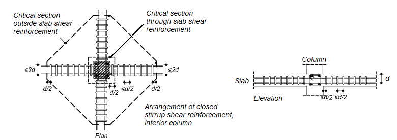
Single-leg, simple-U, multiple-U, and closed stirrups are used as shear reinforcement. Stirrup anchorage and geometry are determined with ACI 25.7.1. Detailed information: Stirrups per ACI 318-19 with ideCAD.
If stirrups are provided, location and spacing are determined with ACI Table 8.7.6.3.
The shear reinforcement engages longitudinal reinforcement at both the top and bottom of the slab, as shown for typical details in ACI Fig. R8.7.6(a) to (c). The shear reinforcement should be symmetrical
about the centroid of the critical section shown in ACI Fig. R8.7.6(d). Spacing limits defined in ACI 8.7.6.3 are shown below.
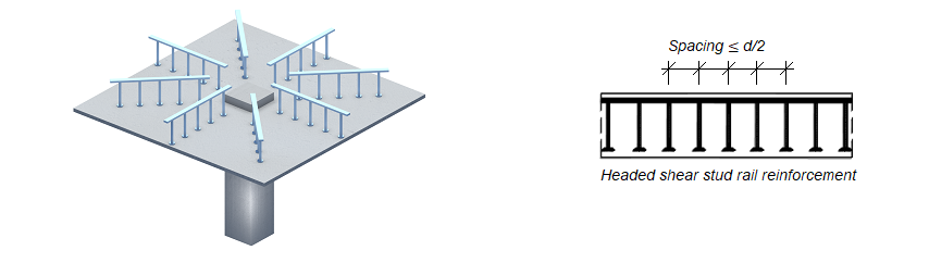
Shear Reinforcement - Headed Studs
According to ACI 8.7.7.1.1, the overall height of the shear stud assembly should be at least the thickness of the slab minus the sum of all given values below;
-
concrete cover on the top flexural reinforcement
-
concrete cover on the base rail
-
One-half the bar diameter of the flexural tension reinforcement
According to ACI 8.7.7.1.2, Headed shear stud reinforcement location and spacing should be in accordance with ACI Table 8.7.7.1.2.