
-
The distributed plastic behavior model in reinforced concrete walls is used to consider nonlinear deformations in a diffuse manner along the entire length of the element.
-
Concrete material is defined by nonlinear two dimensional finite elements, reinforcement material by nonlinear bars Finite element mesh is automatically created to be compatible with reinforcement bars, depending on the condition of confined-uncoated concrete and reinforcement.
-
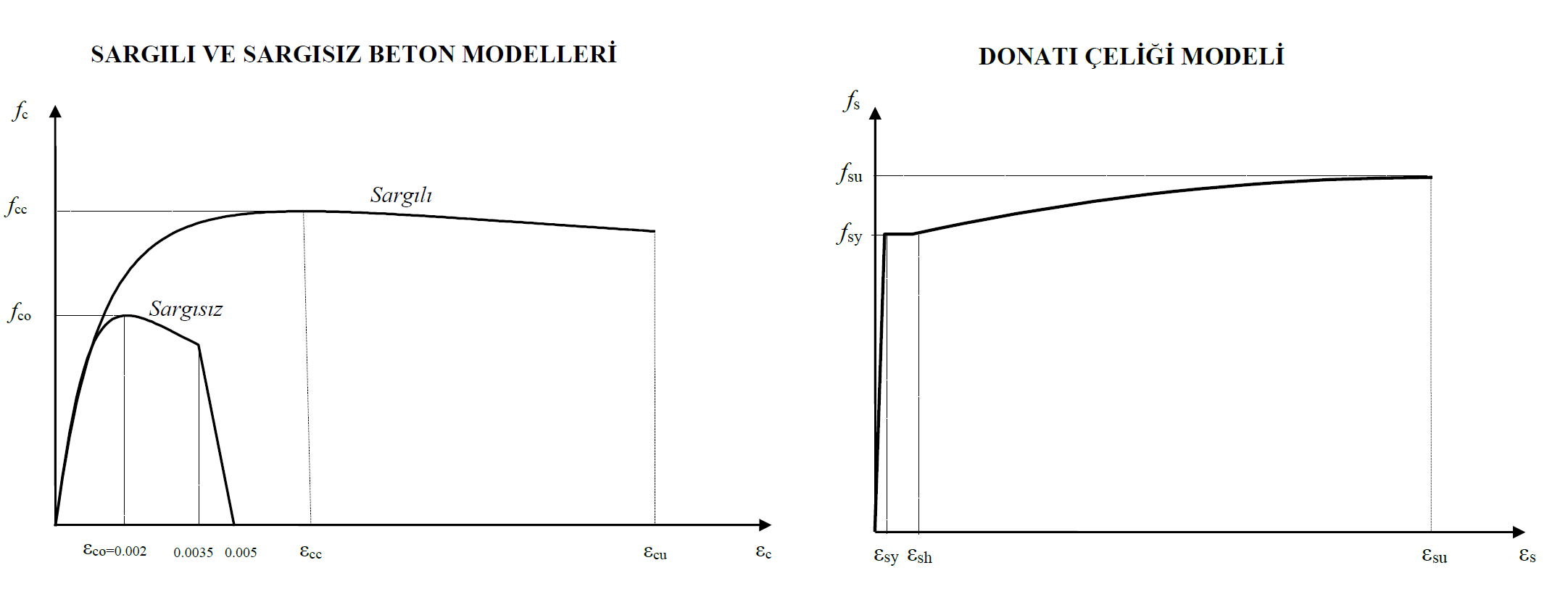
In the distributed plastic behavior model, concrete and reinforcement material models specified in TBDY Appendix 5A are used. In the analysis of new or existing buildings, confined-uncoated concrete and reinforcement models are created automatically.
Notation
Ec = Elasticity module of concrete
Es = Modulus of elasticity of reinforcing steel
E(i) = Elasticity module calculated in the i'th step in the push analysis
fc = Concrete compressive stress in confined concrete
fcc = Confined concrete strength
fck = Characteristic compressive strength of concrete
fco = Compressive strength of unrefined concrete
fs = Stress in reinforcing steel
fsy = Yield strength of reinforcement steel
fsu = Tensile strength of reinforcement steel
fs = Stress in reinforcing steel
fsy = Yield strength of reinforcement steel
fsu = Tensile strength of reinforcement steel
fyw = Yield strength of transverse reinforcement
fyk = Characteristic yield strength of reinforcing steel
σ = Stress
ε = Strain
εc = Concrete pressure strain
εcu = Maximum pressure strain in confined concrete
εs = Deformation of reinforcement steel
εsy = Yield strain of reinforcing steel
εsh = Unit deformation of reinforcement steel at the beginning of hardening
εsu = Reinforcement steel strain at rupture
The diffuse plastic behavior model in reinforced concrete walls is used to consider nonlinear deformations in a diffuse form along the height of the curtain at all floors.
Concrete and reinforcement material are defined according to the material models specified in TBDY ANNEX 5A. Concrete material model is modeled with nonlinear shell finite elements. A confined concrete model is used in the header area of the curtains and an uncovered concrete model is used in the body area. The reinforcement material model is created in harmony with two dimensional finite elements.
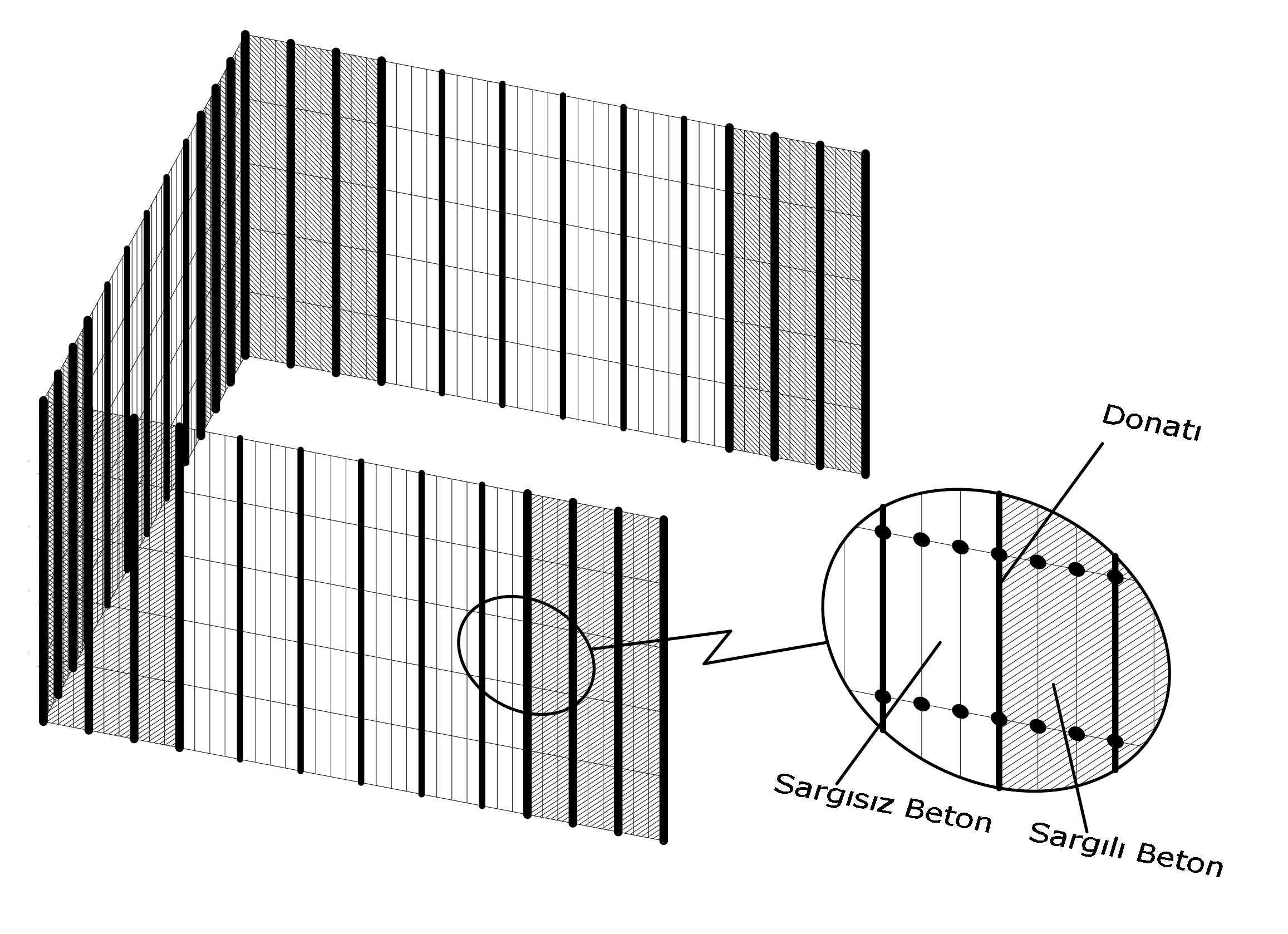
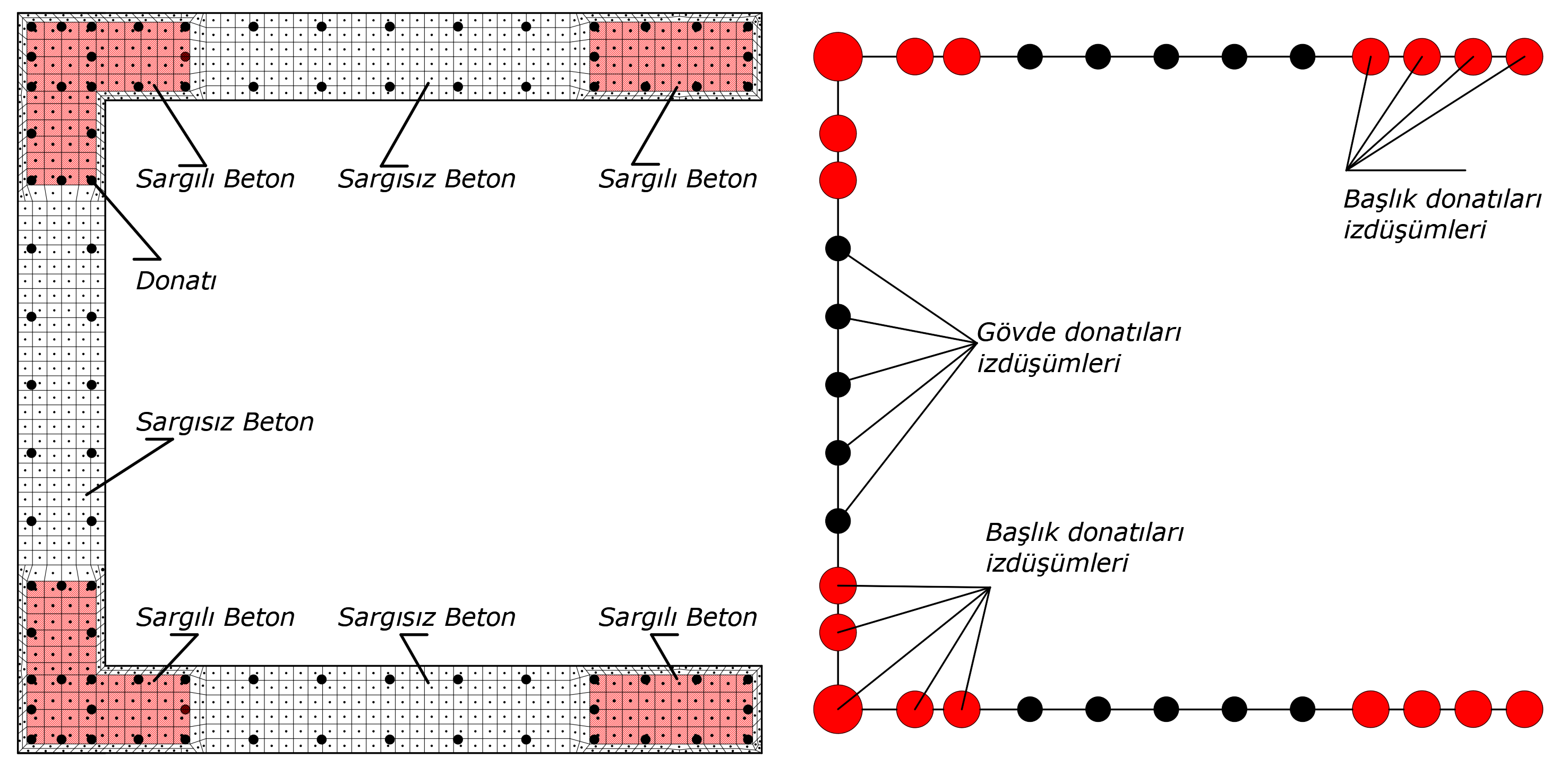
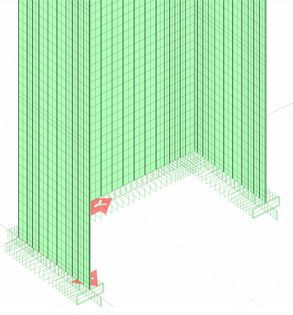
The illustration below shows the representation of finite element and reinforcement models of a U polygon wall. In this picture, the dark bars show the reinforcement elements, the white squares show the non-linear unconfined concrete finite elements, the shaded squares show the non-linear confined concrete finite elements and are defined in the header regions of the curtain.
Reinforcing bars are defined at the nodes of two-dimensional finite elements to ensure harmonious operation.
After defining the coiled-unwound concrete and reinforcing steel finite element models properly, the material stiffness is changed at the end of each pushing step, taking into account the material stress-strain curves, and the structure stiffness matrix is reconstructed.
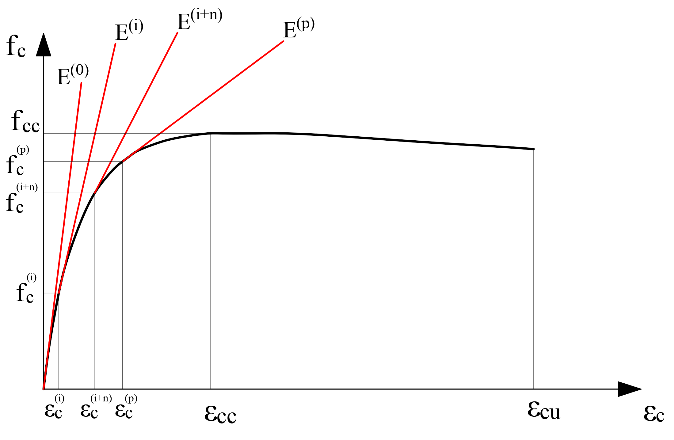
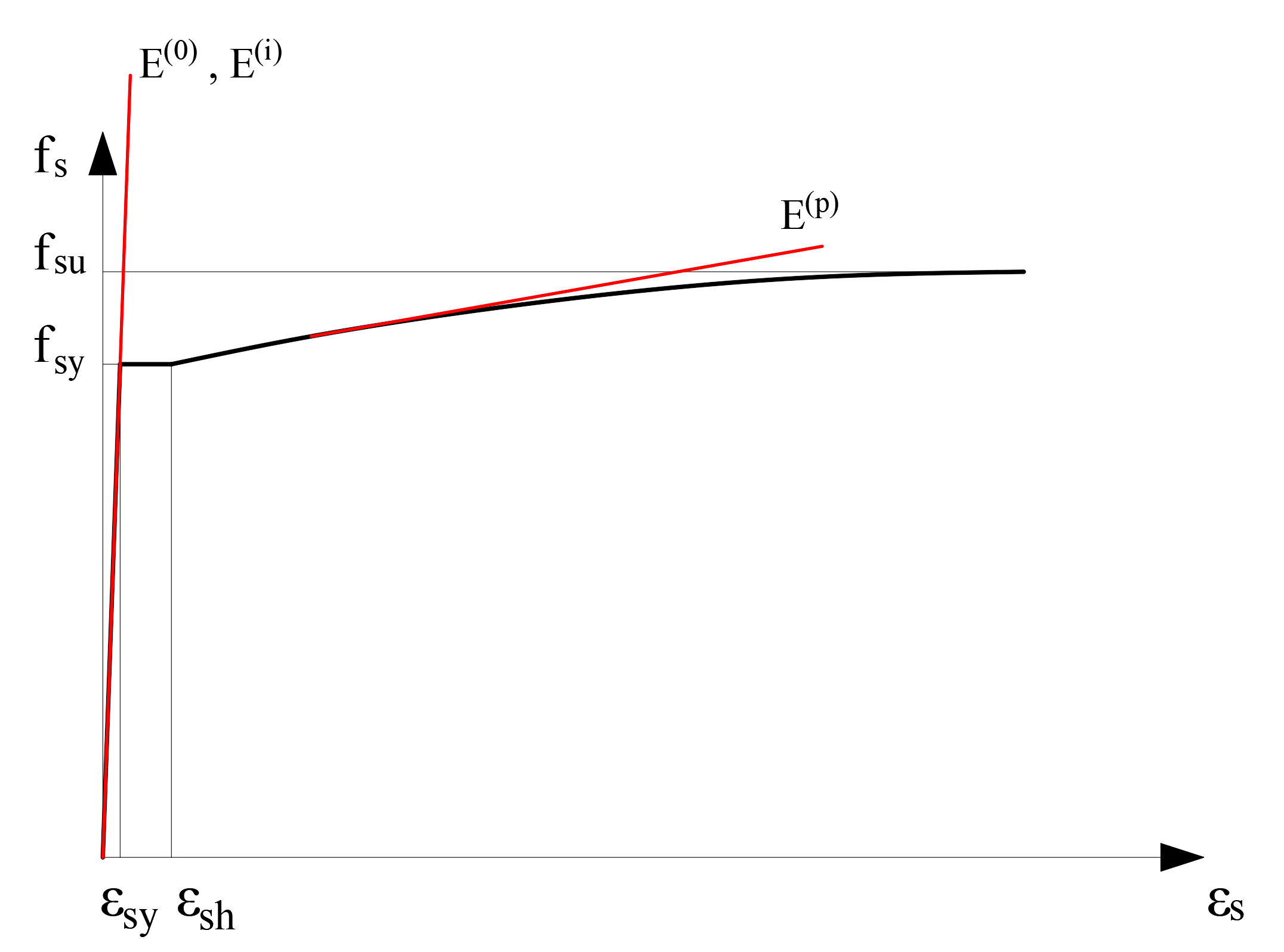
The stress-strain curve that constitutes the concrete material model consists of a strain for each unit deformation value and the elasticity module, which is the slope of the tangent at this point. In the repulsion analysis, the slope in the initial step is shown as E (0), the elasticity module in the i'th step as E (i) and the elasticity module in the last step as E (p). The initial modulus of elasticity varies according to the concrete class. The wall stiffness is reconstructed by reducing the F11 value, which is the axial stiffness of any nonlinear two dimensional concrete finite element in any i'th step, by the value E (i) / E (0). The following picture shows the stress-strain and modulus of elasticity of the wrapped concrete material in each step.
The stress-strain matrix of a two-dimensional finite element defined by an orthotropic material is defined as follows. In this matrix, the terms σ00M and σ11M refer to in-plane axial stresses, σ01M terms to in-plane shear stresses, σ00B and σ11B terms to out-of-plane bending stresses, σ01B to in-plane bending stresses, σ1S and σ2S to out-of-plane shear stresses.
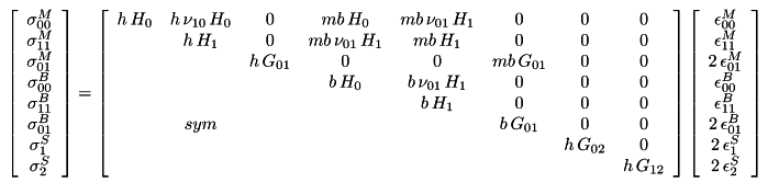
The σ matrix is calculated in terms of different geometric stiffness matrix at each repulsion step, replaced by the appropriate stiffness factor. These terms are reduced by the coefficient E (i) / E (0) in each repulsion step to change the in-plane axial and shear stiffness. As a result of this process, birim values are obtained and the unit deformation values in each step are obtained. In the picture below, terms that are reduced by the coefficient E (i) / E (0) at each step are marked with a red frame in order to vary the in-plane axial and shear stresses.
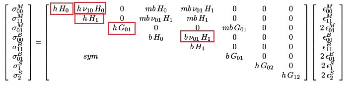
In the scattered plastic behavior model used in nonlinear analysis, the evaluation of the results is made with the unit deformation values. For this reason, verilmektedir values are given in the matrix multiplication above. After the concrete reaches its highest stress value, the stress value remains constant or decreases. However, since the unit deformation value will continue to increase continuously, the term taken into consideration is the value of.
The stiffness and stress of the concrete material under the effect of tension are considered to be zero.
The reinforcement nonlinear reinforcement bar model is obtained by projecting the reinforcement to the middle axis of the wall element in a way that it coincides with the reinforcement area in that area. As indicated in the picture below, the projection of the concrete and reinforcement fibers of a polygon wall, as well as the head and body reinforcement, is shown. Here, the reinforcement areas shown in red represent the reinforcement areas in the header area, while the reinforcement areas shown in black represent the reinforcement areas in the body area.
The reinforcement material model is defined at the nodes of two dimensional concrete finite elements. In this way, two different material models can work in harmony. In the reinforcement steel model, the modulus of elasticity is defined in accordance with the reinforcement stress-strain relation.
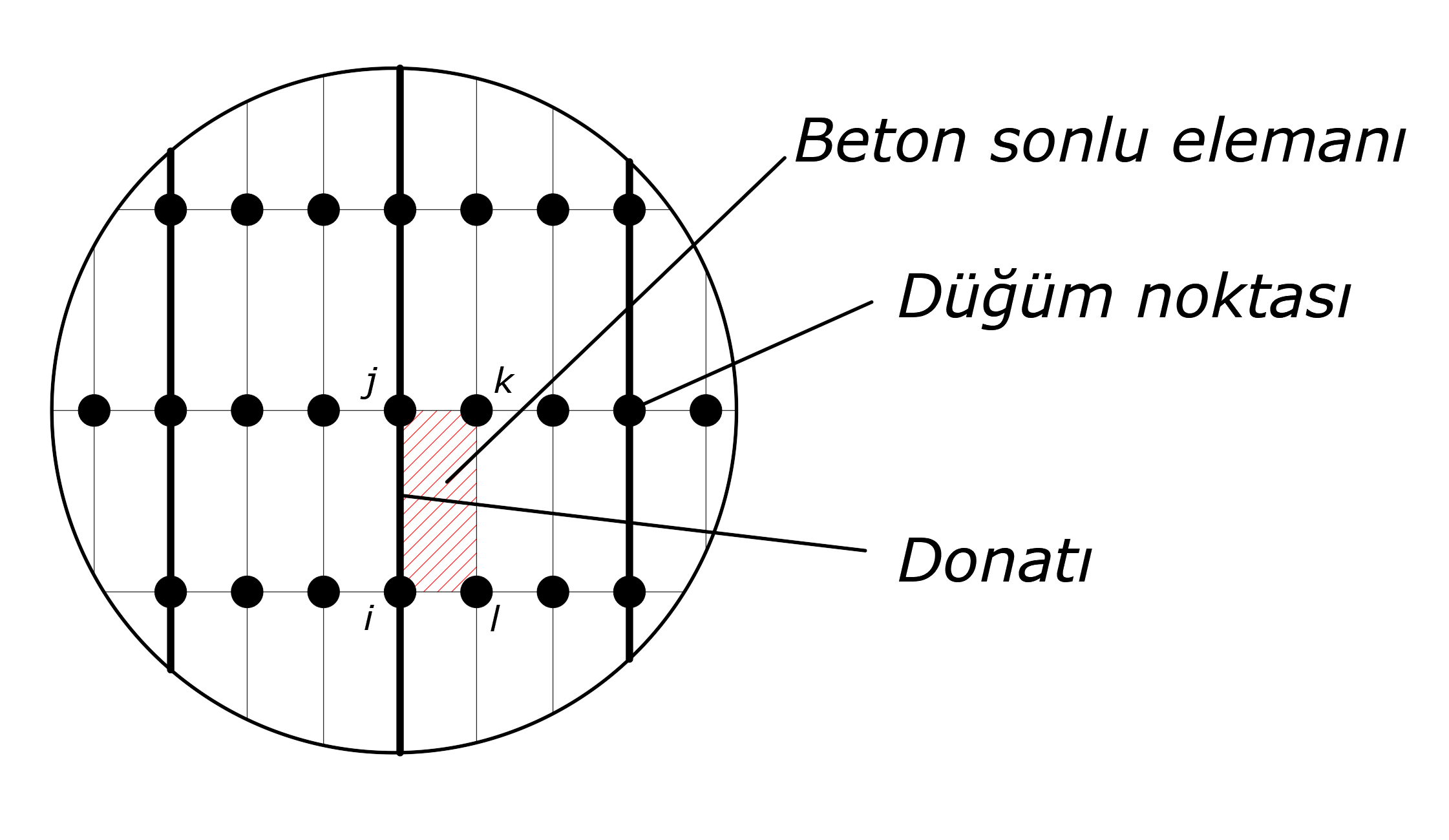
In the picture below, one of the non-linear two-dimensional concrete finite elements is hatched in red and the reinforcement model is shown in bold. The reinforcement material is defined between the nodes i and j in this picture, with the nodes (i, j, k, l) of a rectangular concrete finite element. When calculating the reinforcement strain, the elongation value between joints i and j is obtained by dividing the distance between the initial positions of the i, j joints.
In the polygon wall analysis model shown below, dark colored black lines show the reinforcements and those shown in green indicate two dimensional nonlinear concrete finite elements.
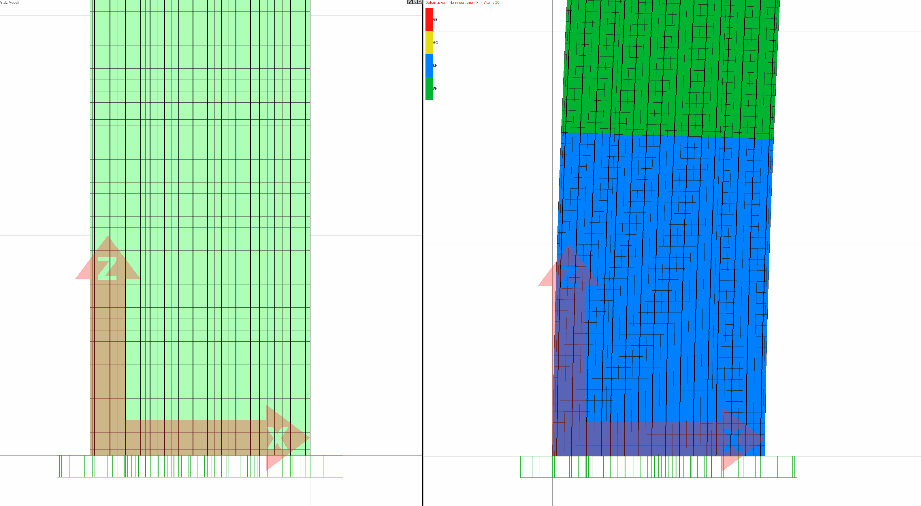
The performance evaluation of the deformed curtain obtained as a result of the analysis is shown in the picture below.
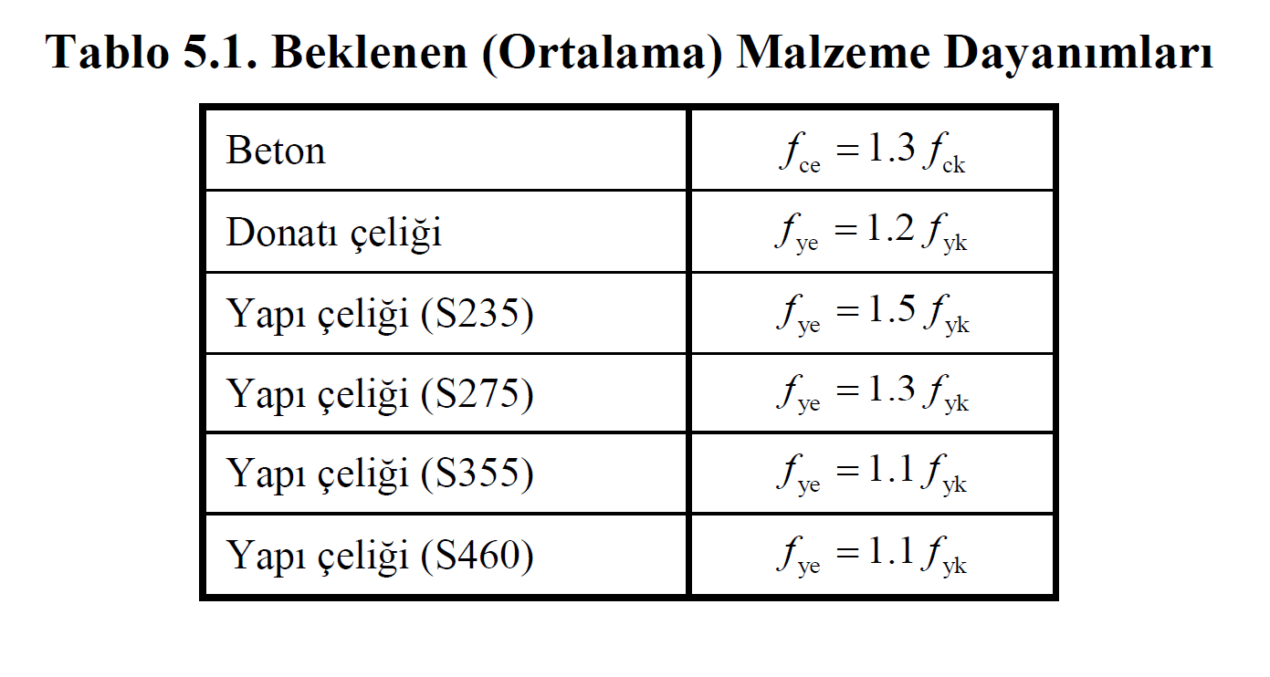
Material models are automatically created for new and existing buildings. The Expected (Average) Material Strengths given in Table 5.1 are used to obtain the stress-strain relationship between the confined-unwrapped concrete model and the reinforcing steel for the new buildings. The wrapped concrete model is automatically created by considering the head area transverse and longitudinal reinforcement status.
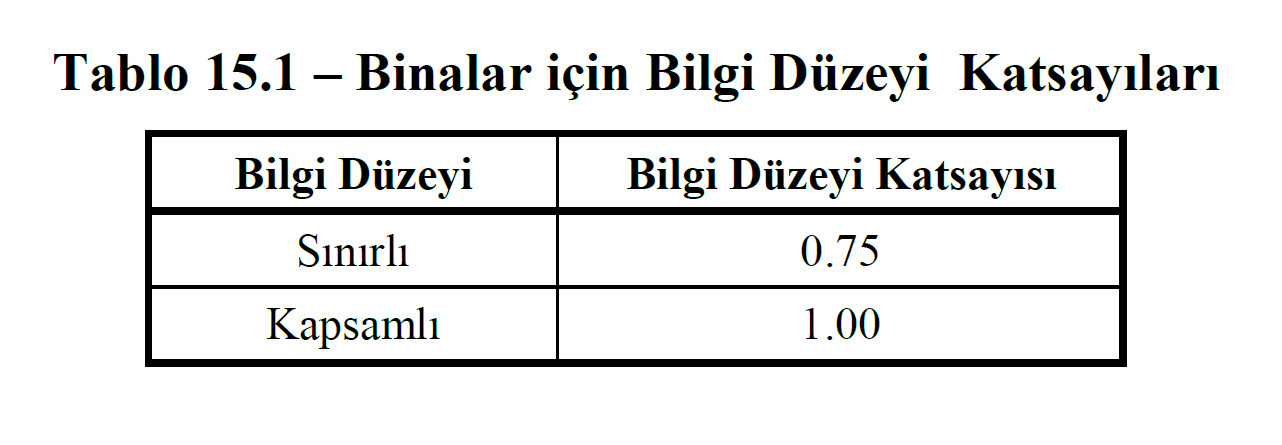
While obtaining the stress-strain relation for the unwound-unwrapped concrete model and reinforcement steel for existing buildings, the Knowledge Level Coefficients are used for the current material strengths given in Table 15.1. Similarly, the confined concrete model is automatically created by considering the head area transverse and longitudinal reinforcement status.
Next Topic
Related Topics