
How ideCAD defines effective section stiffness modifier according to ASCE 7-16?
-
The multiplier values given in ACI Table 6.6.3.1.1(a) are automatically applied for the calculation of earthquake effects.
Both factors given in the table are taken into account in the model. The effective cross-section stiffness factors are only applied to the calculations under the loads included in seismic loads.
Vertical loads indicated by G 'and Q' in earthquake combinations are also again calculated with cracked section stiffness. Moreover, these loads are used in earthquake combinations.
Effective section stiffness is based on the approximate linearization of the nonlinear internal force-deformation relationship (for example, moment-curvature relation) up to flow in a reinforced concrete section to make linear elastic calculations. In the literature, the term cracked section stiffness is also used instead of the term effective section stiffness due to the cracking of concrete in the first stage in the context of nonlinear behavior in the bending effect.
|
Member and Condition |
Moment of inertia |
Cross-sectional area for axial deformations |
Cross-sectional area for shear deformations |
|
|---|---|---|---|---|
|
Columns |
0.70Ig |
1.0Ag |
bwh |
|
|
Walls |
Uncracked |
0.70Ig |
||
|
Cracked |
0.35Ig |
|||
|
Beams |
0.35Ig |
|||
|
Flat plates and flat slabs |
0.25Ig |
|||
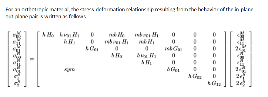
Modeling cracked section properties for structural analysis:
The bending and axial behavior in walls are changed by f11 or f22 depending on the direction of the local axis, and the shear behavior is controlled by f12.
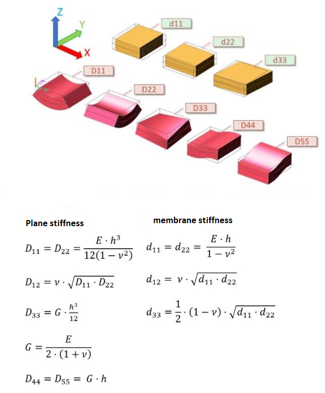
1-1 d11: In-plane axial stiffness (extension) occurring in the (X) axis
2-2 d22: In-plane axial stiffness (elongation) in the (Y) axis
1-2 d12: Stiffness resulting from the combination of "d11" and "d22" stiffnesses (transverse shortening)
3-3 d33: In-plane shear stiffness
4-4 D11: Out-of-plane bending stiffness around the (X) axis
5-5 D22: Out-of-plane bending stiffness around the (Y) axis
4-5 D12: In-plane shear stiffness resulting from the combination of D11 and D22 stiffnesses
6-6 D33: Torsional stiffness
7-7 D44: Out-of-plane shear stiffness in the (X) axis
8-8 D55: Out-of-plane shear stiffness in the (Y) axis