
With the Single Footing Settings command, settings such as single footing size, height, elevation, drawing, material selection, structural material can be accessed.
Location of the Single Footing Settings Dialog
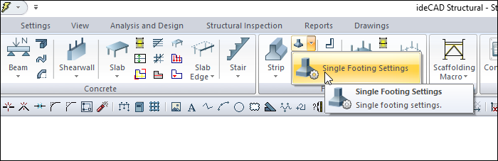
It is available in the Single Footing auxiliary toolbar that appears after the single footing command is run.
You can access it under the ribbon menu Concrete tab Foundation title.
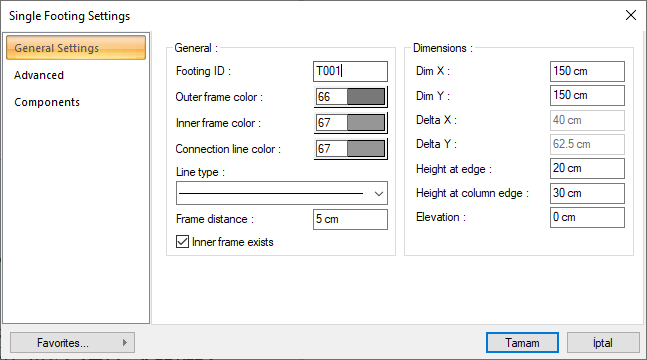
General Settings Tab
|
Specifications |
|---|
|
Footing ID It is the name of the single footing. The letter T is placed in front of the number entered here and the name of the single footing is created and written on the footing in the plan. The number is increased according to the order in which the footings are drawn (such as T1, T2, T3 ....). The single base names can be changed later using the Name Object command. The name index does not have to be T. Different indices can be used for renaming. |
|
Outer frame color The color of the individual base outline (s). The color palette is scrolled by clicking and holding down the left mouse button. The button is released when the desired color is reached. The color box turns into the selected color. If clicked together with the Shift key, the pen thickness of the relevant color can be adjusted. Pen thickness is not noticeable on the screen. The drawing is valid when drawn on paper. |
|
Inner frame color It is the color of the frame around the single footing. The color palette is scrolled by clicking and holding down the left mouse button. The button is released when the desired color is reached. The color box turns into the selected color. If clicked together with the Shift key, the pen thickness of the relevant color can be adjusted. Pen thickness is not noticeable on the screen. The drawing is valid when drawn on paper. |
|
Connection line color It is the color of the lines connecting the inner frame and outer frame corner points. The color palette is scrolled by clicking and holding down the left mouse button. The button is released when the desired color is reached. The color box turns into the selected color. If clicked together with the Shift key, the pen thickness of the relevant color can be adjusted. Pen thickness is not noticeable on the screen. The drawing is valid when drawn on paper. If the connection lines are trapezoidal (if the height at the edge is different from the height at the column level), it is drawn. In cases where the two heights are equal, the connection line is not drawn because the basic will be rectangular. |
|
Line type The line type of the line forming the single footing is selected in the plan. Clicking the down arrow buttons to the right of the boxes opens the list of line types. From this list, the desired line type is selected by clicking with the left mouse button. |
|
Frame distance A frame surrounding the column can be drawn on a single footing where the column rests on a single footing. The distance of the frame from the column face is entered in this box. If the frame is required to be drawn, check the option "There is an inner frame". If this option is not checked, the frame will not be drawn. |
|
Dim X It is the dimension of the single footing parallel to the X dimension of the column resting on it. Column X dimension is the column dimension in the column axis direction. The column axis is the arrow drawn from the column node. If the "Draw column axis" option is selected from Settings/General Settings/Preferences in the classic menu, Settings/Settings/Preferences in the ribbon menu, it appears on the column on the screen. |
|
Dim Y It is the dimension of the single footing parallel to the Y dimension of the column resting on it. The column Y dimension is the dimension perpendicular to the column axis. |
|
Delta X It is the alignment of the single footing in the column local X-axis direction. If the delta X is zero, the left edge of the single footing coincides with the left edge of the column. If positive, the left edge of the single footing shifts to the left by the value entered from the left edge of the column. If negative, the left edge of the single footing shifts to the right by the value entered from the column left edge. The directions should be considered according to the local axis of the column. |
|
Delta Y It is the alignment of the single footing in the column local Y axis direction. If the delta Y is zero, the upper edge of the single footing coincides with the upper edge of the column. If it is positive, the upper edge of the single footing will slide up by the value entered from the upper edge of the column. If negative, the upper edge of the single footing shifts down by the value entered from the upper edge of the column. The directions should be considered according to the local axis of the column. |
|
Height at edge It is the vertical (in z direction) height of the single footing at the edge. If single footings with trapezoidal cross-section are to be made, the footing height at the edge should be smaller than the footing height at the column level. For single footings with rectangular cross section, the heights at the side and at the column level should be equal. |
|
Height at column edge It is the vertical (in z direction) height of the single footing at the level of the column face. If single footings with trapezoidal cross-section are to be made, the footing height at the column level should be greater than the footing height at the edge. For single footings with rectangular cross section, the heights at the side and at the column level should be equal. |
|
Elevation The single footing is higher than the story floor. When the elevation is zero, the upper surface of the single footing coincides with the floor base. If a negative value is entered in the level section, the base floor slides down from the base. Positive values shift the footing up from the floor base. If the individual footing level is changed, the column level on the footing must also be changed accordingly. If not replaced, the column will not sit on the footing. |
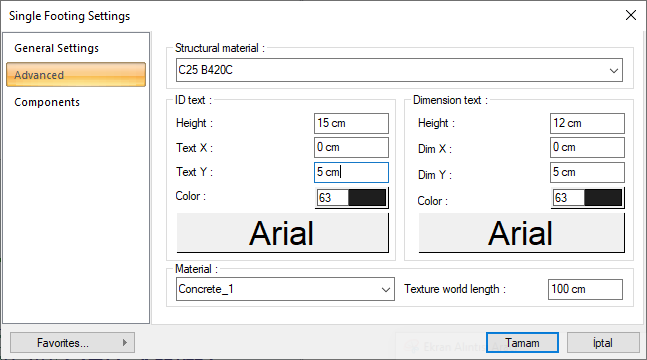
Advanced Tab
|
Specifications |
|---|
|
ID text 
The height of the single footing name text is entered. The color box is slid over the color palette that is opened by clicking with the left mouse button and holding down the button. The button is released when the desired color is reached. The color box turns into the selected color. If clicked together with the Shift key, the pen thickness of the relevant color can be adjusted. If the button just below is clicked, the Font Settings dialog opens. From this dialog, the Column Header Name Text, font is set. Articles are written horizontally. |
|
Dimension text 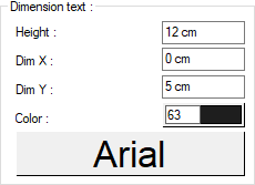
The height of the single footing dimension text is entered. The color box is slid over the color palette that is opened by clicking with the left mouse button and holding down the button. The button is released when the desired color is reached. The color box turns into the selected color. If clicked together with the Shift key, the pen thickness of the relevant color can be adjusted. If the button just below is clicked, the Font Settings dialog opens. From this dialog, the Column Header Size Text, font is set. Articles are written horizontally. |
|
Text X/Text Y X and Y coordinates are entered according to the upper left corner of the column heading of the single footing ID text. Text If the X value is positive, the name text will move to the left, if it is negative, it will move to the right. Text scrolls up if the Y value is positive, and down if it is negative. |
|
Dim X/Dim Y X and Y coordinates are entered according to the upper right corner of the column heading of the single footing dimension text. If the dimension X value is positive, the dimension text shifts to the left, if it is negative, it shifts to the right. If the dimension Y value is positive, the dimension text will scroll up, and if it is negative, it will scroll down. |
|
Material The material to be covered on the footings in the solid model is selected. The base is covered with the selected material and displayed as such in the solid model. Click on the down arrow button with the left mouse button. The appropriate material is selected from the opened material list. If there is no defined item, the list is blank. Adding material is done from the dialog that opens by clicking Settings/Materials line in the classic menu and Settings/Settings/Materials in the ribbon menu. |
|
Texture world length Text length is entered. For example; If 1 meter is entered, the selected material texture is taken as 1 meter and covered on the selected object. Considering that the texture is in the form of a square, the object surfaces are covered with 1x1 textures arranged side by side. |
Components Tab
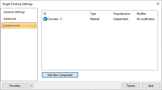
Add Building Components : Assigns the building materials defined for detailed building components metrics to the object.
-
Click the Add building component button.
-
The Component Selection dialog will open.
-
In this dialog, click on the folder related to the material from the list on the left. Click on the material you want to use.
-
Set the parameters on the right.
-
Click the OK button. The "Component Selection" dialog will be closed. A summary line of the material will appear in the Building Components tab. More than one material assignment can be made to an object.
The parameters available in the component selection dialog are:
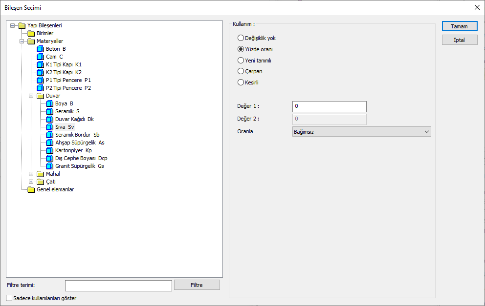
In the usage section
No modification: The amount of material to be assigned for the object in question is marked when it is desired to be used in the size that was previously specified in the material definition.
Percentage: This line is marked when it is desired to be used with the percentage of the amount previously determined in the material definition, as much as the value entered in the "Value 1" line in the same dialog. For example, if the material quantity is 70, if the line “Value 1” says 40, it means the material amount will be used up to 40 * 70%.
Override: This line is marked so that the quantity entered in the “Value 1” line in the same dialog will be used instead of the quantity previously determined in the material definition.
Multiplier: This line is marked in order to use the value found at the end of the multiplication of the value entered in the "Value 1" line in the same dialog with the amount previously determined in the material definition.
Fraction: This line is marked so that the amount determined in the material definition before will be used as the fraction value created by the values entered in the "Value 1" and "Value 2" lines in the same dialog. "Value 1" is the denominator "Value 2" is the denominator.
Proportional to: It is determined to what scale-area, circumference, length etc.-, region-side area, top, edge etc.- the material will be proportioned to. The content of the proportional list box is automatically determined according to the object and the size of the material. For example, a different list will be created if an operation is made for the column, a different list will be created for the library, a different list for the volume, and a different list for the field.
Following are the lines that appear in the Proportion list according to the single footing object and material size.
|
Single Footing |
||
|
Measure |
Listed |
Explanation |
|
Constant |
Independent |
The fixed measure used will be used exactly as the amount. |
|
Length |
Independent |
It means that the length measure found while defining the material will be used exactly as the length value. |
|
Perimeter |
It means that the length of the material will be found by multiplying the perimeter of the single footing with the length measure found while defining the material. |
|
|
Height |
It means that the length of the material will be found by multiplying the length measurement found when defining the material and the height of the single footing. |
|
|
Area |
Independent |
It means that the area measure found while defining the material will be used exactly as the amount. |
|
Volume |
Independent |
The volume measurement found when defining the material will be used exactly as the volume value. |
|
Volume |
It means that the volume measurement found when defining the material will be used by multiplying the floor volume. |
|
|
Count |
Independent |
The number measure found while defining the material will be used exactly as the material number. |
|
Count |
The count measure found while defining the material will be used exactly as the material count. |
|
Next Topic