
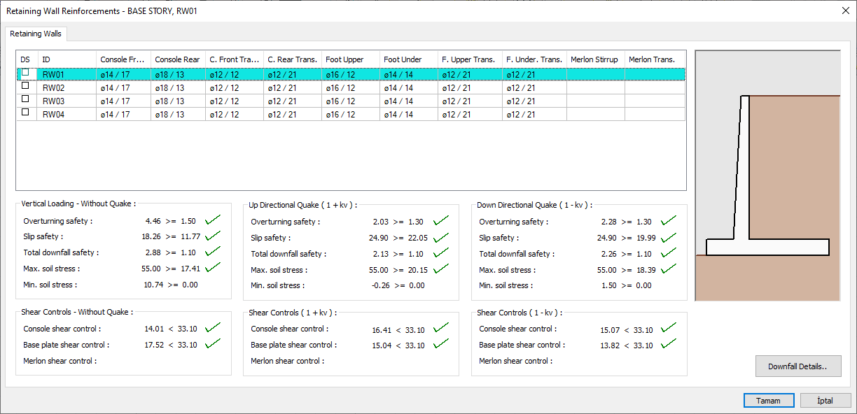
Retaining wall reinforcement design results and inadequacy of individual foundations are displayed in the Retaining Wall Reinforcements dialog. Reinforcement results, rollover and slip safety and total collapse details results are given in the retaining wall reinforcements dialog.
Location of Retaining Wall Reinforcements Dialogue
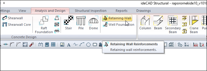
After the Retaining Wall Analysis is done, you can access it by clicking the Retaining Wall command under the Concrete Design heading in the ribbon menu Analysis and Design tab.
Retaining Wall Sections
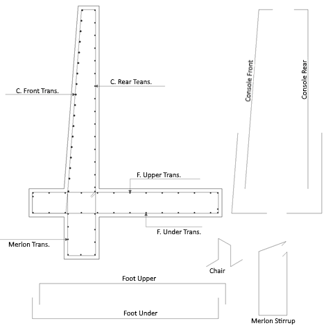
Retaining Wall Reinforcements
|
Specifications |
|---|
|
Retaining wall and rebar list 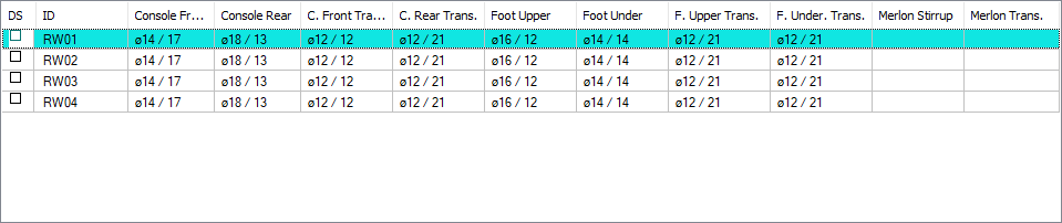
The list of all rebars selected in the retaining wall as a result of the calculation is shown as a table. Rebars were selected automatically by the program. Double click on the cell to change the related rebar. |
|
Preview 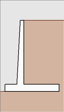
There is a preview of the retaining wall selected from the list. |
|
Vertical loading - without earthquake free 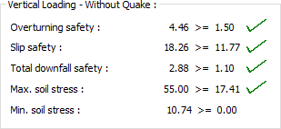
Information on external stability controls obtained as a result of without earthquake loading is printed under this section. |
|
Shear controls - without earthquake 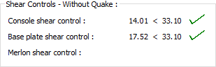
Information on internal stability controls obtained as a result of without earthquake loading is printed under this section. |
|
Up direction quake (1 + kv) 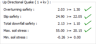
Information on external stability checks obtained as a result of loads in up direction quake conditions are printed under this section. |
|
Shear controls (1 + kv) 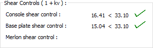
Information on internal stability controls obtained as a result of loads in up direction quake condition is printed under this section. |
|
Down direction quake (1-kv) 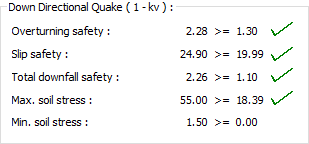
Information regarding the external stability controls obtained as a result of the loads made in the event of a down direction quake is printed under this section. |
|
Shear controls (1-kv) 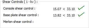
Information regarding the internal stability controls obtained as a result of the loads made in down direction quake conditions are printed under this section. |
|
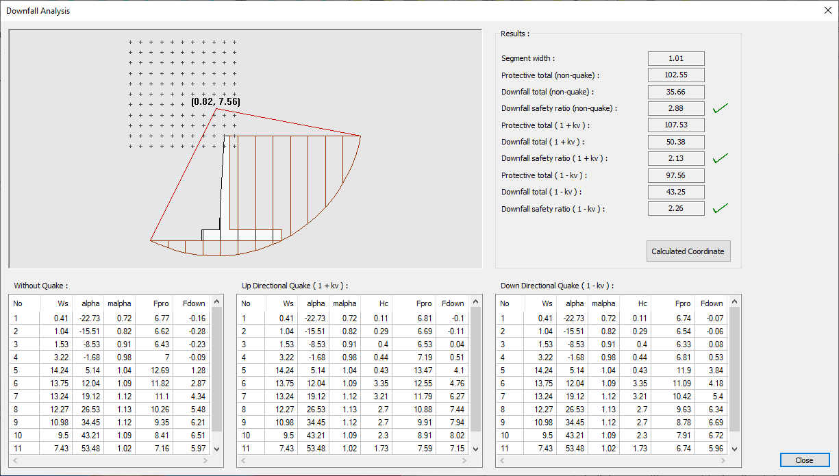
Downfall details A dialogue will open with details of the downfall accounts. |
Downfall Analysis
|
Specifications |
|---|
|
Schematic drawing and coordinate selection area 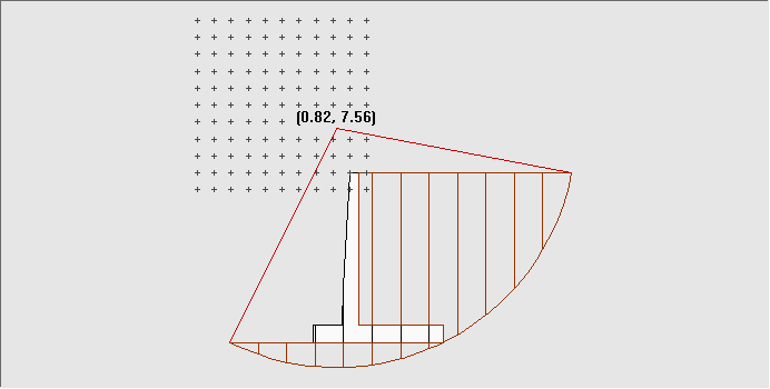
Schematic drawing of the retaining wall. The program makes iterations using the slice method. By clicking on the figure on the screen, the account values for different downfall circle can be displayed. |
|
Without quake 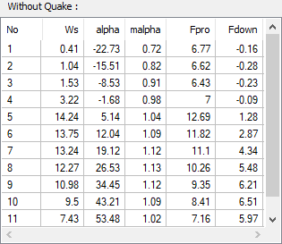
Lists information on downfall circle for without quake situations. |
|
Up directional quake (1 + kv) 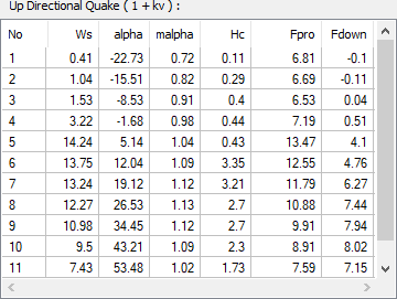
Lists information on downfall circle for up directional quake situations. |
|
Down directional quake (1-kv) 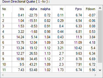
Lists information on downfall circle office for down directional quake situations. |
|
Results 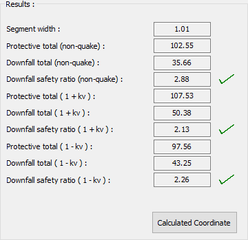
The results of the selected coordinate are listed. |
|
Calculated coordinate By pressing the Calculated Coordinate button, it is possible to display the data of the re-calculated flat. |
Next Topic
Related Topics