
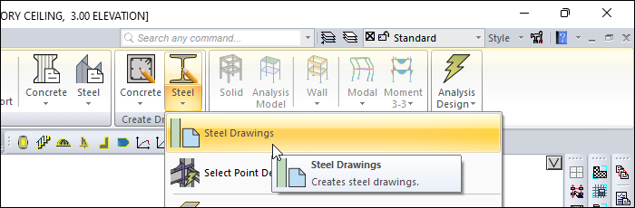
In order to prepare the drawings of the steel elements, you can access the Steel Drawings command from the steel tab create drawings header. Before creating the drawings, by pressing the Settings button, layout settings, scales, fonts, etc. You can access parameters related to steel drawings.
Location of the Steel Drawing Command
You can access it under the Steel tab, Create Drawings heading.
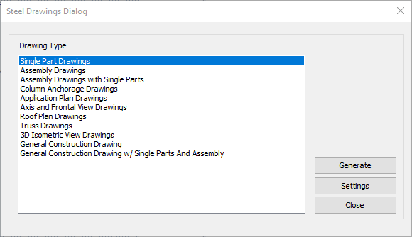
Steel Drawings Dialog
|
Features |
|
Drawing type 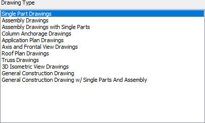
Steel drawing types are listed. The drawing type to be created is selected from the list. |
|
Generate The drawing type selected from the list is created. |
|
Settings Opens the steel drawing settings dialog for the steel drawings. |
|
Close By clicking the button, the steel drawings dialog is closed. |
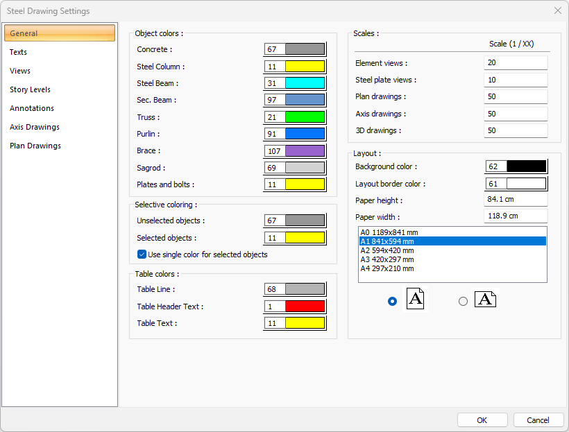
Steel Drawing Settings
General Tab
|
Specifications - Object Colors |
|
Concrete The color of the concrete objects in the drawings is selected. When the color box is clicked, the appropriate color is selected from the window that opens. |
|
Steel Column The color of the steel column objects in the drawings is selected. When the color box is clicked, the appropriate color is selected from the window that opens. |
|
Steel Beam The color of the steel beam objects in the drawings is selected. When the color box is clicked, the appropriate color is selected from the window that opens. |
|
Secondary Beam The color of the secondary beams in the drawings is selected. When the color box is clicked, the appropriate color is selected from the window that opens. |
|
Truss The color of the truss in the drawings is selected. When the color box is clicked, the appropriate color is selected from the window that opens. |
|
Purlin The color of the purlin in the drawings is chosen. When the color box is clicked, the appropriate color is selected from the window that opens. |
|
Brace The color of the braces in the drawings is selected. When the color box is clicked, the appropriate color is selected from the window that opens. |
|
Sagrod The color of the sagrods in the drawings is selected. When the color box is clicked, the appropriate color is selected from the window that opens. |
|
Plates and bolts The color of the plates and bolts in the drawings is selected. When the color box is clicked, the appropriate color is selected from the window that opens. |
|
Specifications - Selective Colors |
|
Unselected objects Color of unselected objects is selected. When the color box is clicked, the appropriate color is selected from the window that opens. |
|
Selected objects The color of the selected objects is selected. When the color box is clicked, the appropriate color is selected from the window that opens. |
|
Use single color for selected objects If the option is selected, single color is used for the selected objects. |
|
Specifications - Table Colors |
|
Table line The color of the table line in the drawings is selected. When the color box is clicked, the appropriate color is selected from the window that opens. |
|
Table header text The color of the table header text in the drawings is selected. When the color box is clicked, the appropriate color is selected from the window that opens. |
|
Table text The color of the table text in the drawings is selected. When the color box is clicked, the appropriate color is selected from the window that opens. |
|
Specifications - Scales (Scale 1 / XX) |
|
Element views The scale value of the element views is entered into the box. |
|
Steel plate views The scale value of the steel plate views is entered in the box. |
|
Plan drawings The scale value of the plan drawings is entered in the box. |
|
Axis drawings The scale value of the axis drawings is entered in the box. |
|
3D drawings Scale value of 3D drawings is entered in the box. |
|
Specifications - Layout |
|
Background color The background color of the drawing screen is determined. |
|
Layout border color The color of the layout border lines is determined. |
|
Paper height The height of the layout is entered in this box. |
|
Paper width The width of the layout is entered in this box. |
|
Standard paper sizes Standard paper sizes are listed. The paper size can be selected from the list, as well as the paper dimensions can be determined by entering the width and height values. |
|
Vertical/Horizontal use It is determined whether the paper will be used horizontally or vertically. |
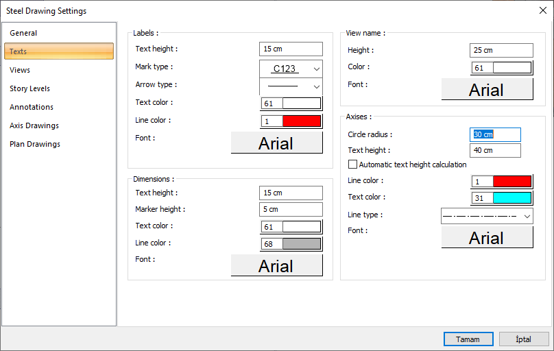
Texts Tab
|
Specifications - Labels |
|
Text height The text height of the labels is entered. |
|
Mark type The mark type of the label is selected. |
|
Arrow type Type of label arrow is selected. |
|
Text color You can choose the color of the label text from the color palette that appears on the screen when you click. If clicked together with the Shift key, the pen thickness of the relevant color can be adjusted. The pen thickness value entered here is only used in inkjet printers. |
|
Line color Sets the color of the tag lines. When the color box is clicked, the appropriate color is selected from the window that opens. |
|
Make The font of the label texts is selected. |
|
Specifications - Dimensions |
|
Text height Size font height is entered. |
|
Marker height The height of the dimension markers is entered. |
|
Text color You can choose the color of the label text from the color palette that appears on the screen when you click. If clicked together with the Shift key, the pen thickness of the relevant color can be adjusted. The pen thickness value entered here is only used in inkjet printers. |
|
Line color Sets the color of the tag lines. When the color box is clicked, the appropriate color is selected from the window that opens. |
|
Make The font of the label texts is selected. |
|
Specifications - View name |
|
Height The height of the view name is entered. |
|
Color Sets the color of the view name. When the color box is clicked, the appropriate color is selected from the window that opens. |
|
Make The font of the label texts is selected. |
|
Specifications - Axises |
|
Circle radius The axis circle radius value is entered. |
|
Text height Text height of the axis is entered. |
|
Automatic text height calculation When the option is checked, text heights are determined automatically according to the circle radius. |
|
Line color Adjusts the color of the axis lines. When the color box is clicked, the appropriate color is selected from the window that opens. |
|
Text color You can choose the color of the axis texts from the color palette that appears on the screen when you click. If clicked together with the Shift key, the pen thickness of the relevant color can be adjusted. The pen thickness value entered here is only used in inkjet printers. |
|
Line type Line type of axis lines is selected. Clicking the down arrow buttons to the right of the boxes opens the list of line types. From this list, the desired line type is selected by clicking with the left mouse button. |
|
Font The font of the label texts is selected. |
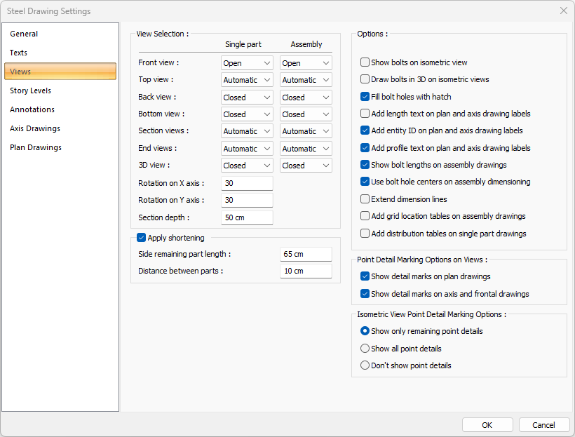
Views Tab
|
Specifications |
|---|
|
Front view In single and assembly drawings, front views are set in this line. The appropriate one among the Open, Closed and Automatic options located under the single and assembly columns is selected. If Open option is selected, front views are drawn in the drawings. Front views are not drawn in the drawings if the Closed option is selected. If the Automatic option is selected, the program decides whether to draw the front views based on the geometry of the elements and the layout. The name of the front views to be displayed in the drawings is written in the box in the view name column. |
|
Top view The setting of the top views in single and assembly drawings is done from this line. The appropriate one among the Open, Closed and Automatic options located under the single and assembly columns is selected. If the Open option is selected, top views are drawn in the drawings. If the Closed option is selected, top views are not drawn in the drawings. If the Automatic option is selected, the program decides whether the upper views should be drawn based on the geometry of the elements and the layout. The name of the top views to be displayed in the drawings is written in the box in the view name column. |
|
Back view The setting of the back views in single and assembly drawings is done from this line. The appropriate one among the Open, Closed and Automatic options located under the single and assembly columns is selected. If the Open option is selected, the back views are drawn in the drawings. If the Closed option is selected, back views are not drawn in the drawings. If the Automatic option is selected, the program decides whether to draw the back views based on the geometry of the elements and the layout. The name of the back views to appear in the drawings is written in the box in the view name column. |
|
Bottom view Setting of the sub views in single and assembly drawings is done from this line. The appropriate one among the Open, Closed and Automatic options located under the single and assembly columns is selected. If the Open option is selected, bottom views are drawn in the drawings. Bottom views are not drawn in the drawings if the Closed option is selected. If the Automatic option is selected, the program decides whether the bottom views should be drawn based on the geometry of the elements and the layout. The name of the bottom views to be displayed in the drawings is written in the box in the view name column. |
|
Section views The setting of section views in single and assembly drawings is made from this line. The appropriate one among the Open, Closed and Automatic options located under the single and assembly columns is selected. If the Open option is selected, section views are drawn in the drawings. If the Closed option is selected, section views are not drawn in the drawings. If the automatic option is selected, the program decides whether to draw the section views based on the geometry of the elements and the layout. |
|
End views The setting of the end views in single and assembly drawings is done in this line. The appropriate one among the Open, Closed and Automatic options located under the single and assembly columns is selected. If the Open option is selected, the end views are drawn in the drawings. End views are not drawn in the drawings if the Closed option is selected. If the Automatic option is selected, the program decides whether or not to draw end views based on the geometry of the elements and the layout. This decision; to create a side view if there is a detail on the element and not to create a end view if there is no detail. |
|
3D view Adjustment of 3D views in single and assembly drawings is done from this line. The appropriate one among the Open, Closed and Automatic options located under the single and assembly columns is selected. If the On option is selected, 3D views are drawn in the drawings. If the Off option is selected, 3D views are not drawn in the drawings. If the Automatic option is selected, the program decides whether to draw the 3D views based on the geometry of the elements and the layout. |
|
Rotation on X axis The rotation angle value of the 3D element image around the X axis is entered in this line. |
|
Rotationon Y axis The rotation angle value of the 3D element image around the Y axis is entered in this line. |
|
Section depth While creating the steel drawings, the section depth value to be taken as basis is entered. |
|
Apply shortening In long element drawings, non-detail sections are shown shorter by applying a shortened representation. This way the drawings can take up less space. |
|
Side remaining part length It determines the length of the part shown in detail. |
|
Distance between parts Determines the distance between parts in the section where abbreviated representation is applied. |
|
Show bolts on isometric view Bolt holes are also shown in isometric view. |
|
Show bolts on isometric view When marked, it draws the bolt hole gaps in the steel drawings as hatched. |
|
Add length text on plan and axis drawing labels The lengths of the elements on the plan and axis are also written. |
|
Add entity ID on plan and axis drawing labels The names of the objects are also written on the plan and axis. |
|
Add profile text on plan and axis drawing labels The names of the profiles are also written on the plan and axis. |
|
Show bolt lengths on assembly drawings Bolt lengths are also shown in the assembly drawings. |
|
Use bolt hole centers on assemly dimensionin When marked; While dimensioning in assembly drawings, the measurement reference point is taken as the middle of the bolt holes. |
|
Extend dimension lines When marked, the dimension line is extended to the reference point while dimensioning the steel drawings. |
|
Add grid location tables on assembly drawings It adds the axis and position information where the assembly element will be placed in the plan to the block in the assembly drawings. |
|
Add distribution tables on single part drawings In single part drawings, it adds the assembly part information and the number of each part to the tables. |
|
Show detail marks on plan drawing If the option is selected, point detail names are shown on the plan drawings. |
|
Show detail marks on axis and frontal drawings If the option is selected, point detail names are shown on axis and frontal drawings. |
|
Show only remaining point details If the option is selected, only the remaining point details are shown in 3D isometric view drawings. |
|
Show all point details If the option is selected, all point details are shown in 3D isometric view drawings. |
|
Don’t show point details If the option is selected, point details will not be shown in 3D isometric view drawings. |
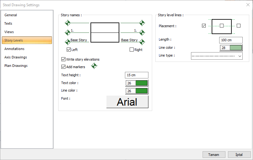
Story Levels Tab
|
Specifications - Story names |
|
Story names 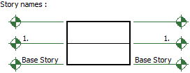
It is the options that show how the story names will be displayed in section or view. |
|
Left 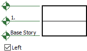
Writes the story names to the left of the section or view plane. |
|
Right 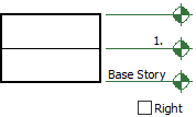
Writes the story names to the right of the section or view plane. |
|
Write story elevations On the floor lines, it shows the floor heights in parallel with the number of floors and their total value |
|
Add markers Adds jeans mark above fold lines. |
|
Text height Story names are the text height of their writing. The larger the value, the larger the text size. |
|
Text color Story names are the text color of their writing. A color is selected from the color palette that is opened by clicking the color box. |
|
Line color It is the linetype of the line that shows the story alignments. An appropriate type is selected from the line type list. |
|
Font Story names are the fonts of their text. |
|
Specifications - Story level lines |
|
Story level lines These are the options that regulate the story level lines. Determine how the story lines are to be displayed in appearance by marking the regions given in the figure. |
|
Placement Story level lines are shown visually, depending on the selection. Make your selection by clicking the left mouse button. |
|
Length It determines how long story level lines will be drawn out of the section or view plane. |
|
Line color It is the color of story level lines. A color is selected from the color palette that is opened by clicking the color box. |
|
Line type It is the line type of story level lines. An appropriate type is selected from the line type list. |
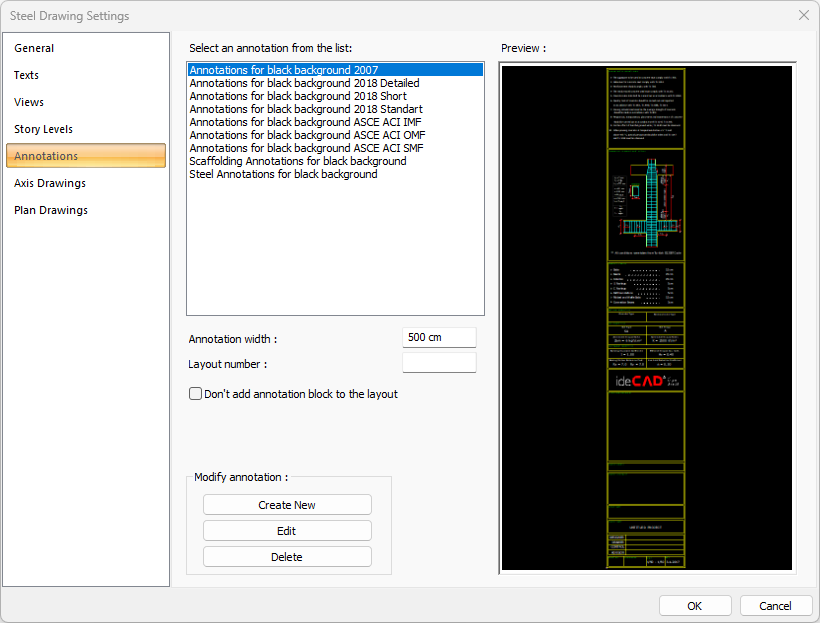
Annotations Tab
|
Specificatios |
|
Select an annotation from the list 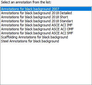
You can choose the ready-made annotations in the list for your steel drawing paper. |
|
Preview 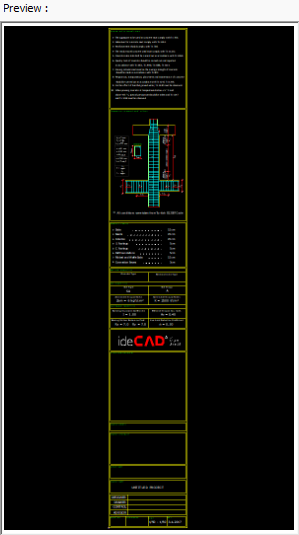
There is a preview of the annotation selected from the list. |
|
Annotation width Annotation width is determined. |
|
Layout number The layout number is determined. |
|
Create new The new annotation is created. |
|
Edit Selected annotation is edited. |
|
Delete Annotation is deleted. |
|
Don’t add annotation block to the layout If it is checked, annotation will not be added to the layouts. |
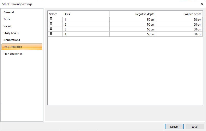
Axis Drawings Tab
|
Features and Descriptions |
|
Select The axis to be included in the drawing is selected. |
|
Axis 
Indicates the name of the axis. |
|
Negative depth 
Negative depth distance is specified in the axis drawing. |
|
Positive depth 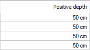
Positive depth distance is specified in the axis drawing. |
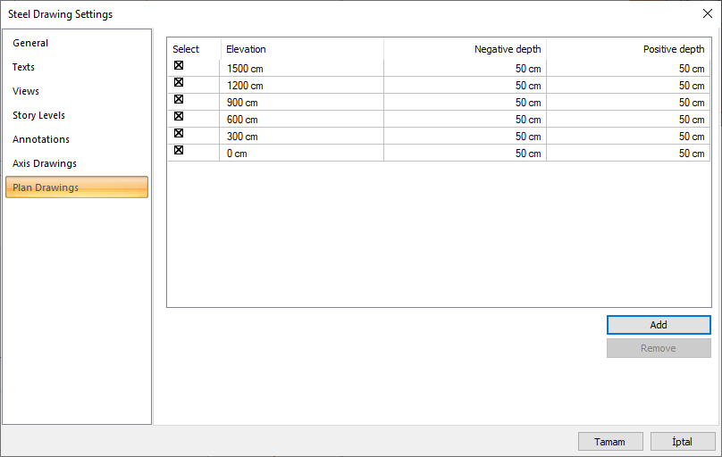
Plan Drawings Tab
|
Specifications |
|
Select Indicates the plan elevation to be included in the drawing. |
|
Elevation 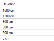
The elevation of the plan drawing is determined. |
|
Negative depth 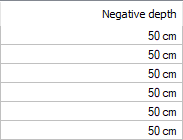
The negative depth in the plan drawing is determined. |
|
Positive depth 
The positive depth in the plan drawing is determined. |
|
Add A new plan drawing is added. |
|
Remove The plan drawing is deleted. |
Next Topic