
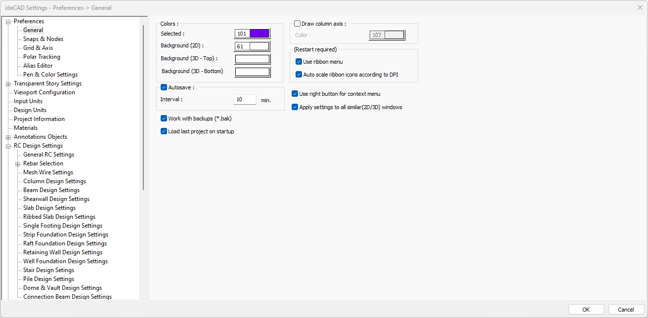
In the General tab, general properties such as node snap factor, pen and color settings, grid settings, axis borders are adjusted. Many settings can be accessed from the general, snap & nodes, grid & axis, polar tracking, alias editor, pen & color settings sections.
General
|
Specifications |
|---|
|
Selected Traces are created on the selected objects to show that they have been selected. In this option, the color of these traces is set. Whichever color was set, the object takes on that color when it is selected. |
|
Background (2D) The color of the 2D worksheet is set. |
|
Background (3D- Top) The color of the top of the 3D worksheet is adjusted. |
|
Background (3D- Bottom) The color of the bottom of the 3D worksheet is adjusted. |
|
Autosave 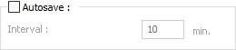
By checking the autosave option, the project will be automatically backed up at the specified interval. Project backups will be automatically saved to the folder where the main file is located during the run. |
|
Work with backups (* .bak) By activating the option, a copy of the previous version of the project with bak extension is created during the project registration process. |
|
Load last project on startup If checked, the last worked project will be loaded automatically when the ideCAD is opened. |
|
Draw column axis The color of the line indicating the major direction of the column is adjusted. If the option is selected, this line is shown in the plan. |
|
Use ribbon menu If checked, it works with the ribbon menu layout and if unchecked, it works with the classic menu layout. After the option is changed, you have to exit the ideCAD and run it again in order to use the selection. |
|
Auto scale ribbon icons according to DPI It allows to automatically adjust the ribbon menu icon sizes according to the resolution of your computer screen. It helps to solve the problem that icons appear small on high resolution screens. |
|
Use right button for context menu If this option is selected, the right menu opens when the right mouse button is pressed. When the mouse is hovered over an object and the right mouse button is clicked, a list of the most used commands related to the object will be opened. If the option is not selected, the right mouse button will work as a command repeat. |
|
Apply settings to all drawing windows It will ensure that the settings made for the current drawing window will also be valid for other currently open windows. |
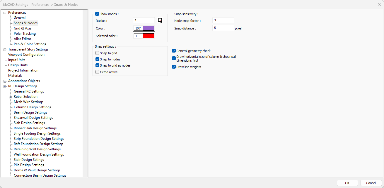
Snaps & Nodes
|
Specifications |
|---|
|
Show nodes It allows the node points to be visible in the plan or not. If checked, nodes are visible in the plan and not visible if not marked. |
|
Radius In case the node points are shown, the diameter of the visible in the plan is set on this line. Its unit is pixel. |
|
Color In the case where the node points are shown, the color shown in the plan is selected. |
|
Selected color In case the nodes of the selected object are shown, the color shown in the plan is selected. |
|
Node snap factor During node selection, the distance to click is set. If the mouse cursor is around the node snap factor near the node, it allows the node to be selected by clicking the left button. |
|
Snap distance During the object selection, the distance to be clicked is adjusted. If the mouse cursor is around the object's snap distance setting, you can select the object. The value entered here also affects the difficulty / ease of selection (its unit is pixel). |
|
Snap to grid Used for the cursor to catch the intersection points of the grid lines. Mark the line for locking possibility. |
|
Snap to nodes Used for the cursor to jump (snap) to nodes. Check the locking facility line. |
|
Snap to grid as nodes Check if you want the cursor to catch the grid points while in object mode. |
|
Ortho active Check if you want to turn on ortho mode. Vertical mode provides ease of drawing objects at 0 and 90 degrees. |
|
General geometry check Mark for automatic general geometry check. It is recommended to keep the line marked in order to immediately avoid possible errors (geometric errors) that may be encountered while drawing. |
|
Draw horizontal size of column & shearwall dimensions first When this option is selected, in places where column and shearwall names are written such as formwork, column application, report, the dimension of the column and shearwall dimensions parallel to the x axis is written first. For example, let's define a column that is 25 vertical and 60 cm horizontal. We can define the ideCAD possibilities as we want by rotating this column. When this option is checked, the column dimensions will be written as 25/60 regardless of how the definition is made. |
|
Draw line weights When this option is selected, it allows objects drawn with different line thicknesses to be displayed on the plan plane with the same thickness they were drawn on. |
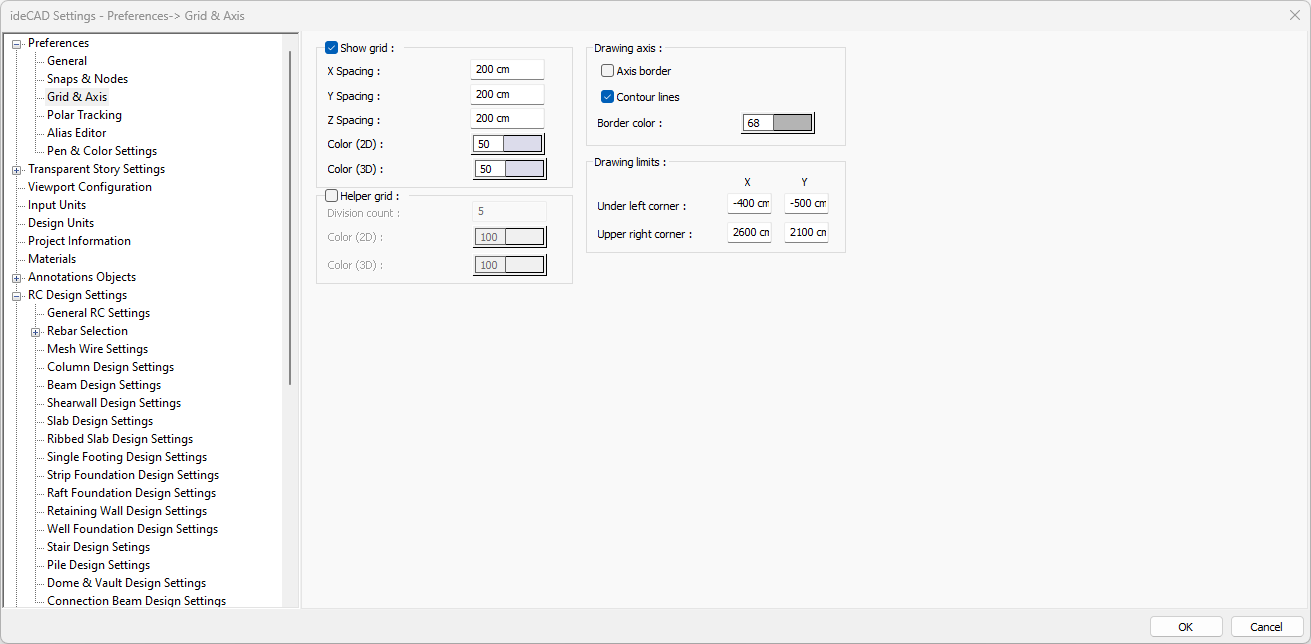
Grid & Axis
|
Specifications |
|---|
|
Show grid The grid lines are made visible by checking the option. |
|
X/Y/ Z spacing 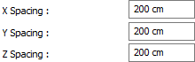
Spacing values are entered for grid lines in X, Y and Z planes. |
|
Color (2D) The color of the grid lines is selected for 2D windows. |
|
Color (3D) The color of the grid lines is selected for 3D windows. |
|
Helper grid By checking the option, helper grid become visible between the grid lines. |
|
Division count The distance between the helper grid lines is entered. |
|
Color (2D) The color of the helper grid is selected for 2D windows. |
|
Color (3D) The color of the helper grid is selected for 3D windows. |
|
Axis border The axis limits are made visible by selecting the option. |
|
Contour lines Contour lines are made visible by checking the option. |
|
Border color The axis border and the color of the border lines are selected. |
|
Drawing limits 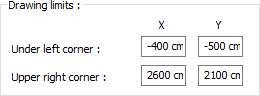
Drawing limits are determined by entering values for the lower left and upper right corners. |
Polar Tracking
|
Specifications |
|---|
|
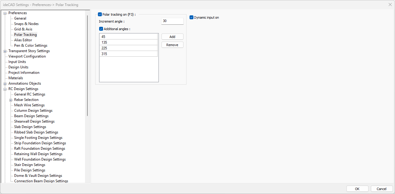
Polar tracking on (F3) Activates polar tracking mode. In any drawing command, when the cursor is moved after the first point is given, the cursor snaps to defined angles. |
|
Increment angle Determines the angles that the cursor will snap to with an increment of the entered angle value. For example, given the increment angle 30, polar tracking works for 0, 30, 60, 90,120.150 etc angles. |
|
Additional angles 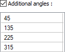
Activates polar tracking for additional angles other than increment angle. Polar tracking is also activated for additional angles. |
|
Add Adds additional angle. |
|
Remove Additional angle deletes. |
|
Dynamic input on It allows entering angle and length information at the same time without using the coordinate box while entering the object. |
Alias Editor
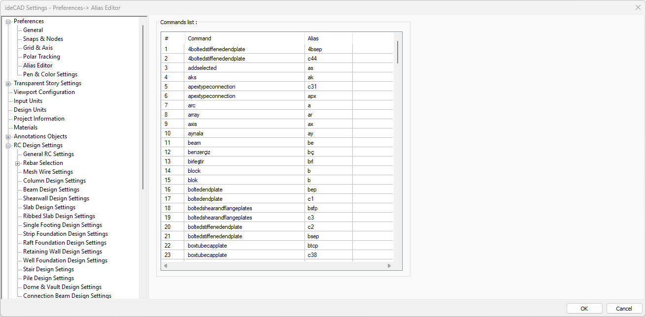
The Alias Editor dialog lists the commands in the ideCAD and their shortcuts. Shortcuts can be changed if desired.
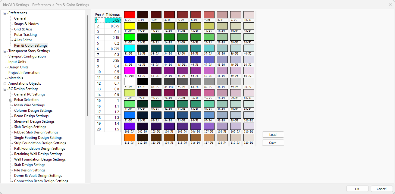
Pen & Color Settings
|
Specifications |
|---|
|
Pen# and Thickness 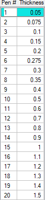
Item numbers and corresponding pen thicknesses are listed. The values in the thickness column are in millimeters and can be changed. |
|
Colors 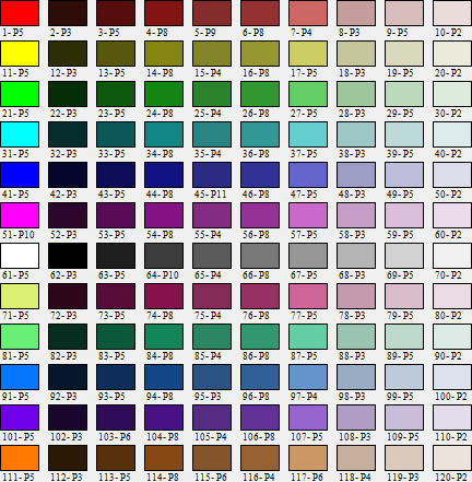
The colors defined in the ideCAD are listed. There are numbers in the form of (1-P5), (12-P12) under each color box. The number on the left (1, 12, 113 etc.) indicates the position of the relevant color on the color palette, and the number on the right (P1, P11 etc.) indicates the item number assigned to the corresponding color. The colors and pen numbers of the boxes can be changed by the user. |
|
Load Previously saved pen and color settings are loaded. |
|
Save Pen and color settings are saved for later use. |
Next Topic