
The Complete Message:
Relative floor displacement in (X / Y) direction is high, increase system rigidity
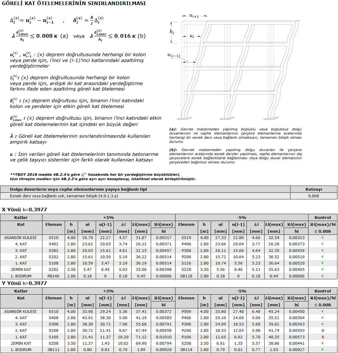
The relative floor displacement control is carried out in accordance with the principles given under the heading of Effective Relative Floor Displacement Calculation and Limitation in the article 4.9.1 of TBDY 2018 .
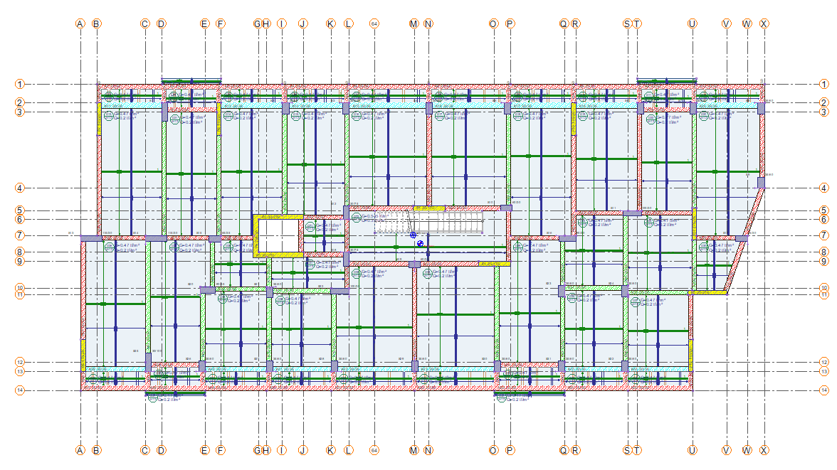
Sample relative floor displacement report and sample floor plan:
You can follow the steps listed below for possible solutions by examining the relative floor displacement report:
-
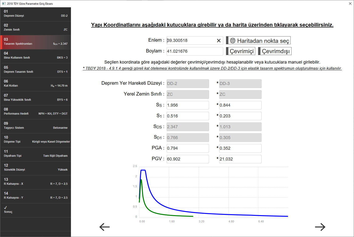
Check the building coordinates.
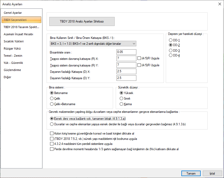
Since the λ coefficient is cross in the control of relative storey drifts, the magnitude of the value is effective for relative storey displacements. The λ coefficient value is obtained from the elastic spectrum DD2 and DD3 depending on the earthquake ground motion level. For this reason, it is important that the coordients of the structure are correctly defined for both DD2 and DD3. Make sure that both structure coordinates and parameters based on coordinates are given correctly.
Structure coordinates are given in Analysis Settings / 2018 TBDY Analysis Settings Wizard.
-
See what direction and for which download is not provided by reviewing the report
In the sample relative floor displacement report, relative floor displacement controls are not provided at the 2nd and 1st floors in the Y direction + 5% (Modal E3) loading.
-
katta → λ * δ
i(max) / hi = 0.009858> 0.008
-
katta → λ * δ
i(max) / hi = 0.01010> 0.008
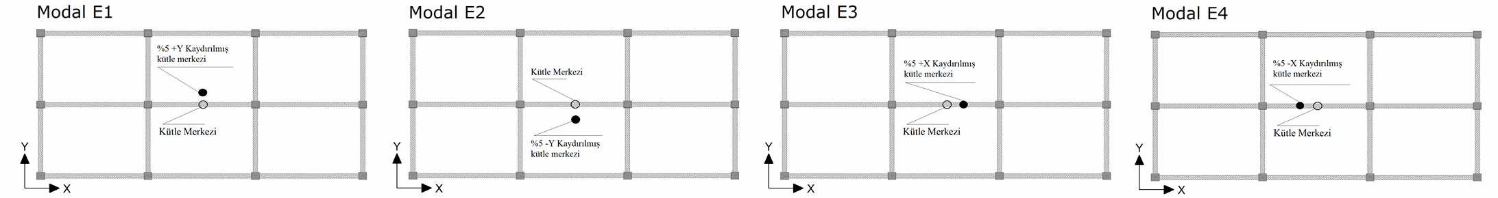
According to the schematic representation of the + 5% Modal E3 loading, it refers to the right of the center of mass. For this reason, it is understood that it is necessary to add a carrier system in the Y direction and / or to rotate the columns, as it is on the right side of the structure and has a Y direction.
Changing the direction of column dimensions to balance 5% eccentricity loadings and / or not adding curtain / curtain group in that direction is a suitable way to solve.
-
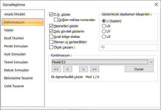
Get an idea about the behavior of the building by examining the deformation of the structure.
When Modal E3 loading is examined for the sample structure, it can be seen which part of the building is subjected to more displacement, in accordance with the information given in the 2nd.
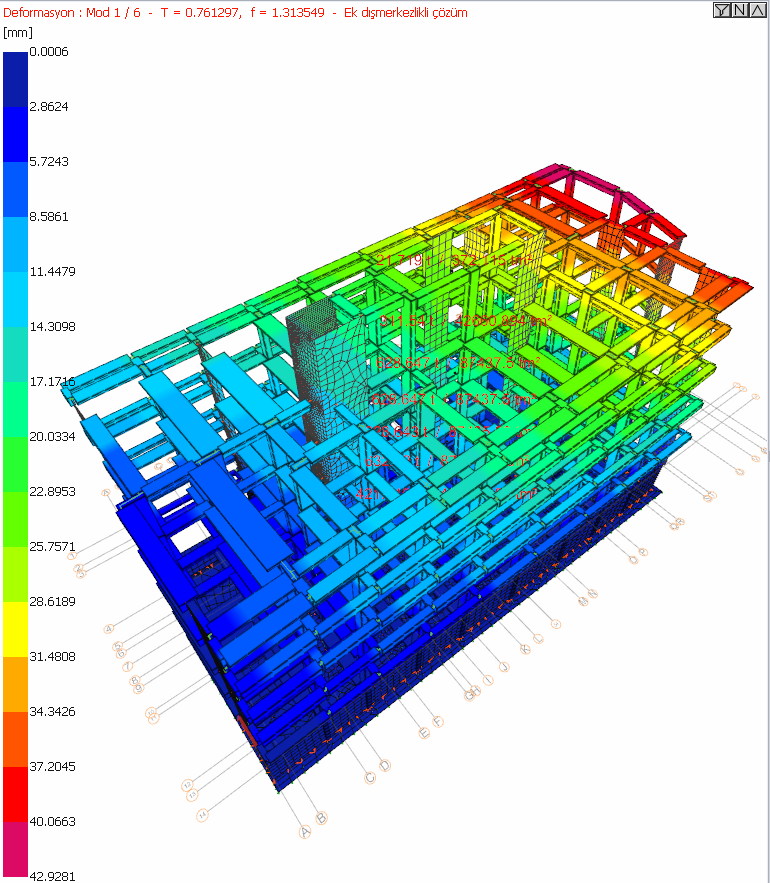
According to the sample perspective view, it is seen that the displacements are more at the right end of the structure than at the left side of the structure. For this reason, it is understood that it is necessary to add a carrier system in the Y direction and / or to rotate the columns, as it is on the right side of the structure and has a Y direction.
-
In thin and long structures, if you make the carrier system strong in the short direction, it will help to ensure the relative floor displacement
-
Flaky frames have a negative effect. Making the frame continuous by adding beams at the axles where the frame is discontinuous can help to provide relative story offsets.
-
If the superstructure-foundation interactive solution is made, the floor horizontal coefficient is effective. Check if it has been entered correctly. In cases where the superstructure-foundation interactive solution is made, increasing the foundation thickness can help provide relative story offsets.
-
Increasing the beam dimensions can contribute to the relative story offset.
-
Provided that it is built on site , TBDY may consider applying Article 4.9.1.3b . There is an option in the analysis settings. Application of TBDY Article 4.9.1.3b increases the relative floor offset upper limit by 2 times.
Related Topics