
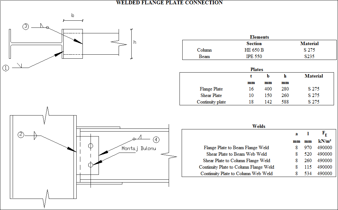
How does ideCAD design Welded Flange Plate Connections according to AISC 360-16?
-
Design limit states of welded flange plate connections are calculated automatically according to AISC 360-16.
Symbols
Ag: Gross area
An: Net cross-section area
Ae: Effective net cross-sectional area
Avg: Gross area under shear stress
Anv: Net area under shear stress
Ant: Net area under tensile stress
Aw: Cross-section web area
bbf = width of beam flange, in. (mm)
bp = width of end-plate, in. (mm)
d = depth of connecting beam, in. (mm)
g = horizontal distance between bolts, in. (mm)
dh: Bolt hole diameter
Fy: Structural steel characteristic yield strength
Fu: Structural steel characteristic tensile strength
nsp: Number of slip planes
K: Effective length factor
L: Connector distance
tbf = thickness of beam flange, in. (mm)
tp = thickness of end-plate, in. (mm)
w = Size of weld leg, in. (mm)
Rn: Characteristic strength
Rnwl: Total nominal strength of longitudinally loaded fillet welds
Rnwt: Total nominal strength of transversely loaded fillet welds,
Connection Geometry
GEOMETRY CHECK
Flange Plate to Beam Flange Weld Size
The minimum size of fillet welds is checked according to AISC 360-16 Table J2.4
|
w ≥ wmin |
|
|
|
|
w |
11.315 mm |
|
√ |
|
wmin |
6 mm |
Table J2.4 |
√ |
Shear Plate to Beam Web Weld Size
The minimum size of fillet welds is checked according to AISC 360-16 Table J2.4
|
w ≥ wmin |
|
|
|
|
w |
11.315 mm |
|
√ |
|
wmin |
5 mm |
Table J2.4 |
√ |
Shear Plate to Column Flange Weld Size
The minimum size of fillet welds is checked according to AISC 360-16 Table J2.4
|
w ≥ wmin |
|
|
|
|
w |
11.315 mm |
|
√ |
|
wmin |
5 mm |
Table J2.4 |
√ |
Continuity Plate to Column Flange Weld Size
The minimum size of fillet welds is checked according to AISC 360-16 Table J2.4
|
w ≥ wmin |
|
|
|
|
w |
11.315 mm |
|
√ |
|
wmin |
6 mm |
Table J2.4 |
√ |
Continuity Plate to Column Web Weld Size
The minimum size of fillet welds is checked according to AISC 360-16 Table J2.4
|
w ≥ wmin |
|
|
|
|
w |
11.315 mm |
|
√ |
|
wmin |
6 mm |
Table J2.4 |
√ |
STRENGTH CHECKS
Flange Plate to Beam Flange Weld Strength
The nominal and design strength of the weld is checked according to AISC 360-16.
|
Lwı |
760 mm |
AISC 360-16 J2.4(c) |
|
Lwt |
210 mm |
|
|
Fe |
490 N/mm2 |
|
|
Rnwl |
|
|
|
Rnwt |
|
|
|
Rnw |
|
|
|
w |
11.315 mm |
|
|
Fu-plate |
360 N/mm2 |
|
|
Fu-flange |
360 N/mm2 |
|
|
tp |
16 mm |
|
|
tf |
17.2 mm |
|
|
RnBM |
|
|
|
Rn |
|
|
|
ΦRn |
|
|
|
Required |
Available |
Ratio |
Control |
|---|---|---|---|
|
505.682 kN |
1140.426 kN |
0.296 |
√ |
Flange Plate Tension Yield
The limit state of tension plate yield is checked according to AISC 360-16.
|
Ag |
|
|
|
Fy |
275 N/mm2 |
|
|
Rn |
|
AISC 360-16 (J4-1) |
|
ΦRn |
|
|
|
Required |
Available |
Ratio |
Control |
|---|---|---|---|
|
505.682 kN |
1108.8 kN |
0.456 |
√ |
Flange Plate Tension Rupture
The limit state of the flange plate tension rupture is checked according to AISC 360-16.
|
An |
|
|
|
Ae |
|
|
|
Fu |
410 N/mm2 |
|
|
U |
1.00 |
|
|
Rn |
|
AISC 360-16 (J4-2) |
|
ΦRn |
|
|
|
Required |
Available |
Ratio |
Control |
|---|---|---|---|
|
505.682 kN |
1377.6 kN |
0.367 |
√ |
Flange Plate Block Shear
The block shear limit state is checked according to AISC 360-16.
|
Ag |
|
|
|
Anv |
|
|
|
Ant |
|
|
|
Fy |
275 N/mm2 |
|
|
Fu |
410 N/mm2 |
|
|
Ubs |
1.0 |
|
|
|
|
|
|
Rn |
|
AISC 360-16 (J4-5) |
|
ΦRn |
|
|
|
Required |
Available |
Ratio |
Control |
|---|---|---|---|
|
505.682 kN |
2538 kN |
0.199 |
√ |
Flange Plate Compression Yield
The limit state of compression plate yield is checked according to AISC 360-16.
|
K |
0.65 |
|
|
L |
20 mm |
|
|
r |
4.619 mm |
|
|
KL / r |
2.81 |
|
|
Fy |
275 N/mm2 |
|
|
Ag |
|
|
|
Rn |
|
AISC 360-16 (J4-6) |
|
ΦRn |
|
|
|
Required |
Available |
Ratio |
Control |
|---|---|---|---|
|
505.682 kN |
1108.8 kN |
0.456 |
√ |
Shear Plate to Column Flange Weld Strength
The nominal and design strength of the weld is checked according to AISC 360-16
|
w |
11.315 mm |
|
FE |
490 N/mm2 |
|
l |
260 mm |
|
e |
117.5 mm |
|
Rn |
|
|
ΦRn |
|
|
Required |
Available |
Ratio |
Control |
|---|---|---|---|
|
135.975 kN |
498.69 kN |
0.273 |
√ |
Shear Plate to Beam Web Weld Strength
The nominal and design strength of the weld is checked according to AISC 360-16
|
Fe |
490 N/mm2 |
|
|
w |
11.315 mm |
|
|
Fu |
360 N/mm2 |
|
|
t |
11.1 mm |
|
|
Rnw |
|
|
|
RnBM |
|
AISC Manual 14th 8-12 |
|
Rn |
|
|
|
ΦRn |
|
|
|
Required |
Available |
Ratio |
Control |
|---|---|---|---|
|
579.254 kN/m |
1764 kN/m |
0.328 |
√ |
Web Plate Shear Yield
The nominal and design yield strength of the web plate is checked according to AISC 360-16
|
Ag |
|
|
|
Fy |
275 N/mm2 |
|
|
Rn |
|
AISC 360-16 J4-3 |
|
ΦRn |
|
|
|
Required |
Available |
Ratio |
Control |
|---|---|---|---|
|
135.975 kN |
429 kN |
0.317 |
√ |
Web Plate Shear Rupture
The limit state of the web plate shear rupture is checked according to AISC 360-16.
|
Anv |
|
|
|
Fu |
410 N/mm2 |
|
|
Rn |
|
AISC 360-16 J4-3 |
|
ΦRn |
|
|
|
Required |
Available |
Ratio |
Control |
|---|---|---|---|
|
135.975 kN |
372.69 kN |
0.365 |
√ |
Web Plate Flexural Yield
The limit state of the web plate shear yield is checked according to AISC 360-16.
|
dp |
260 mm |
|
Fy |
275 N/mm2 |
|
tp |
10 mm |
|
a |
117.5 mm |
|
Rn |
|
|
ΦRn |
|
|
Required |
Available |
Ratio |
Control |
|---|---|---|---|
|
135.975 kN |
273.948 kN |
0.496 |
√ |
Column Panel Zone Shear
The welded flange plate connection's panel zone shear limit state is checked according to AISC 360-16.
|
Pr |
1621.397 kN |
AISC 360-16 J10-9 |
|
Py |
|
|
|
Fy |
275000 kN/m2 |
|
|
Ag |
28634.759 mm2 |
|
|
dc |
650 mm |
|
|
tw |
16 mm |
|
|
Rn |
|
|
|
ΦRn |
|
|
|
Required |
Available |
Ratio |
Control |
|---|---|---|---|
|
56.746 kN |
1544.4 kN |
0.037 |
√ |
Next Topic