
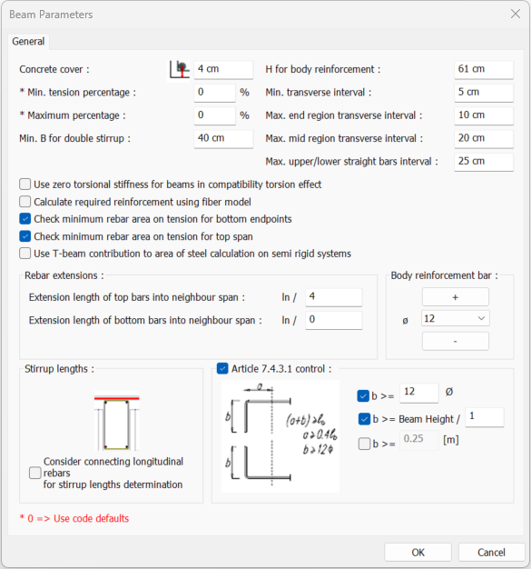
With the Beam Parameters command, the design parameters used in the Concrete Beam Design are determined. Concrete cover, maximum and minimum stirrup interval and percentage etc. parameters are determined from the beam parameters window. The option to calculate the required reinforcement in beams with the fiber model is also available in this window.
Location of the Beam Parameters Dialog
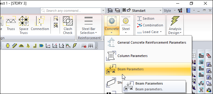
Ribbon menu Analysis and Design tab Design Parameters title under the Beam Parameters by clicking on the command Beam Parameters can be found in the dialogue.
Beam Parameters
It determines with parameters which criteria the program will comply with in concrete design and rebar placement stage.
In parameters marked with ( * ), the text 0 “zero” means that the value specified in the design code is used.
Parameters with the ( % ) sign mean the percentage expression of the rebar ratio. It is the ratio of the cross-sectional area of the reinforced concrete element to the rebar area expressed as a percentage.
For example, when a “1” is written to the minimum percentage parameter, the rebar percentage is considered 1%. Since the percentage equivalent of a 0.01 rebar ratio is 1%, it is appropriate to write “1” to this parameter.
|
Specifications |
|---|
|
Concrete cover It is the distance from the center of gravity of the tension or compression rebar inside the beam to the outer face of the concrete. |
|
Min. tension percentage The rebar percentage determines the minimum value of the rebar that is to be placed in the tension zone in the beam. The percentage value of the gross area of the beam specified in this parameter determines the minimum rebar area. This parameter is used at the bottom of the beam and the top of the beam support. The minimum rebar area of the concrete element means that the gross section will not be less than the percentage value entered with this parameter. In parameters marked with ( * ), the text 0 “zero” means that the value specified in the design code is used. |
|
Maximum percentage The rebar percentage determines the maximum value of the rebar that is to be placed in the tension zone (upper rebar in support, lower rebar in the span) in the beam. The percentage value of the gross area of the beam specified in this parameter determines the maximum rebar area. The maximum rebar area of the concrete element means that the gross section will not exceed the percentage value entered with this parameter. In parameters marked with ( * ), the text 0 “zero” means that the value specified in the code used is used. |
|
Min. B for double stirrup The beam width is compared with this parameter. As long as the beam width does not exceed the minimum width specified in this parameter, the beams are rebar with a double arm stirrup. Otherwise, they are equipped with 2 double-armed stirrups. Rebar is made for all beams in the project. Also, if the double stirrup option is selected in the structural/concrete tab in the beam settings dialog, that beam is rebar with a double stirrup regardless of the min. B parameter for double stirrups. In other words, for which beam or beams this adjustment is made, double stirrups are thrown on only those beams and beams. |
|
H for body reinforcement If the beam height is more than the value specified in this parameter, the body rebar is placed on the beam. |
|
Min. transverse interval The spacing of the stirrup to be placed in the beam wrapping area is selected not less than the value specified in this parameter. |
|
Max. end region transverse interval The spacing of the stirrup to be placed in the beam wrapping area is selected so that it is not more than the value specified in this parameter. |
|
Max. mid region transverse interval The spacing of the stirrup to be placed in the beam mid region is selected so that it is not more than the value specified in this parameter. |
|
Max. upper/lower straight bars interval The beam width is divided by the value written in this line and the minimum assembly or flat rebar range to be placed on the beam is determined according to this value. In all conditions, at least two 12-gauge straight and assembly rebar are placed on the beam. In cases of double stirrups or bringing more than 2 rebars, the program selects straight and the number of assemblies as much as possible. For example, in a beam that requires 4 assemblies, 4 straight erbars are tried to be placed. |
|
Body reinforcement bar 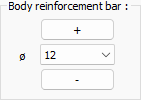
User is the diameter of the body rebar to be placed on the beams. |
|
Use zero torsional stiffness for beams in compability torsion effect If marked use zero torsional stiffness for beams in compability torsion effect, and the beam torsional moment of inertia is taken as zero. |
|
Calculate required reinforcement using fiber model If marked, the required longitudinal reinforcement area in reinforced concrete beams is calculated by defining appropriate concrete and reinforcement models and section fibers in the beam cross section. |
|
Check minimum rebar area on tension for bottom endpoints If it is marked, the minimum rebar area on tension for bottom endpoint of the support is controlled. |
|
Check minimum rebar area on tension for top span If it is marked, the minimum rebar area on tension for top span is controlled. |
|
Extension length of top bars into neighbour span The value of the part of the continuous beams whose top rebars are connected to the support, to be extended into the adjacent beam, depending on the beam clear span is determined from this line. |
|
Extension length of bottom bars into neighbour span The value of the part of the continuous beams whose bottom rebars are connected to the support, to be extended into the adjacent beam, depending on the beam clear span is determined from this line. |
|
Use T-beam contribution to area of steel calculation on semi rigid systems If marked, in the semi-rigid systems, T-beam contribution is used to area of steel calculation. |
|
Article 7.4.3.1 control 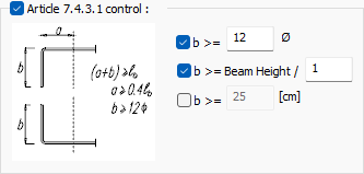
If TDY article 7.4.3.1 will be checked, this option is selected. With this control, the program checks the adequacy of the beam longitudinal rebars extended into the side columns. The minimum conditions are written in the diagram and can be changed if desired. |
|
Consider connecting longitudinal rebars for stirrup lengths determination 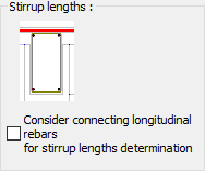
While calculating the length of the beam stirrup, it is thought that it will be placed so as to surround the flat rebar at the bottom with the mounting at the top. When this option is checked, it is assumed that the flat rebars coming from the adjacent beam, if any, together with the top assembly are also included in the stirrup. As a result, the stirrup length is calculated with allowance for the rebars coming from the neighboring entrance at the top and the opening is drawn in that way. |
Next Topic