
In order to carry out linear performance analysis in existing structures , the conditions specified in TBDY 15.5.3 and calculated by impact/capacity ratios (ECO) must be met. If any of the application conditions of linear performance analysis is not met, one of the nonlinear methods should be chosen.
-
In the evaluation of existing buildings, the application limits of linear calculation methods are checked automatically.
-
The calculation method (linear or nonlinear calculation methods) of performance analysis is under user control.
ICONS
BYS = Building Height Class
EKO = Impact / Capacity ratio
R a = Earthquake Load Reduction Coefficient
Linear calculation methods according to TBDY Section 15.5 can be used in determining the earthquake performance of existing buildings with the Assessment and Design Based on Shaping (ŞGDT) approach . However, in order to apply the linear calculation methods , the conditions described in the Article 15.5.3.1 of the TBDY that are linked to the Impact / Capacity Ratio (ECO) values must be met. The ECO value is the ratio of the internal force value consisting of vertical loads and earthquake loads ( loading conditions ) taken as R a = 1 to the cross-sectional capacity calculated by considering the Knowledge Level Coefficient and Available Material Strengths .
The following (a) , (b) , (c) , (d) or (e) any of the material to form applicable in case of straight-line basis in the performance analysis.
(a) Building Height Class defined in TBDY Section 3.3 and determined according to Table 3.3 is less than 5 (BYS <5).
(b) The presence of B3 type irregularity specified in Article 3.6.2.4 of TBDY .
(c) The average ECO values of vertical ductile elements (column, curtain) for the earthquake direction (X) and (Y) at any floor other than the top floor of the building , scaled with the shear force described in Article 15.5.3.2 , are based on the average ECO values of beams in the earthquake direction. to be great.
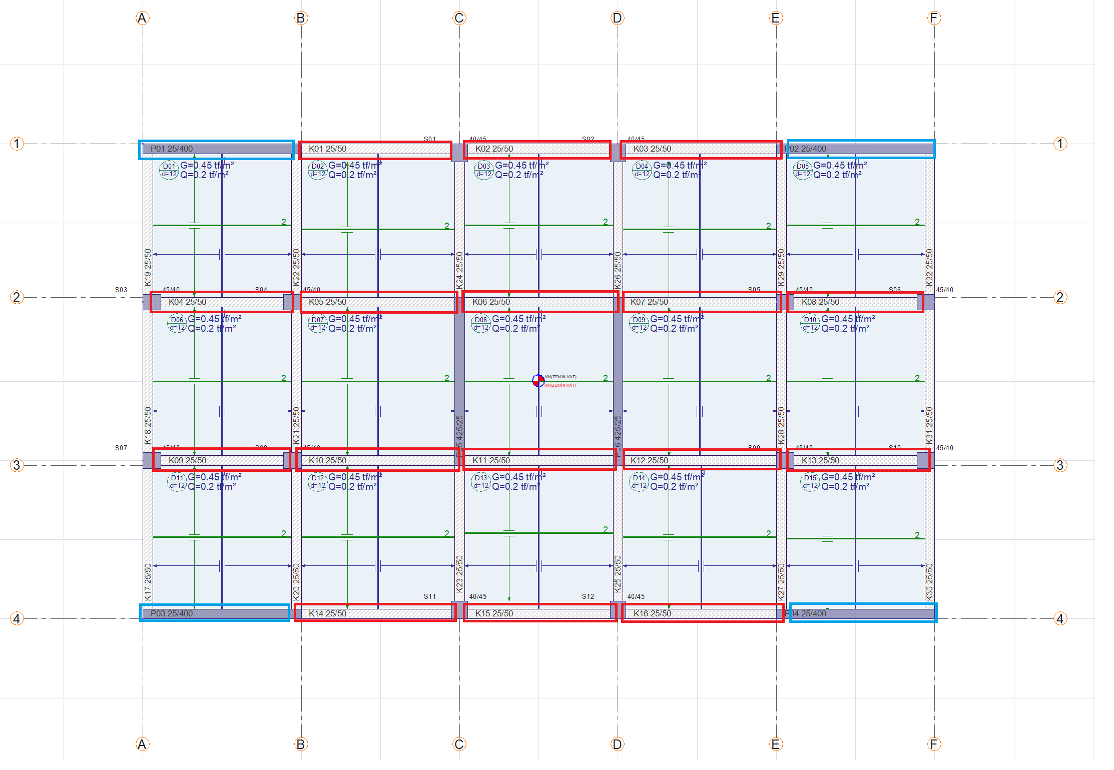
In the picture above (X) the beams with average ECO values for the earthquake direction are marked in red. (X) For the earthquake direction, the average ECO values of the beams marked in red are compared with the ECO values scaled by the shear force of the vertical ductile elements. While calculating the ECO value scaled by the shear force of the walls (X), the curtains marked in blue are taken into consideration for the earthquake direction. While the ECO value scaled by the shear force of the columns is found (X), the internal force values in this direction for the earthquake direction are divided by the capacities in the earthquake direction (X).
Similar operations are carried out for the earthquake in the (Y) direction.
(d) For any floor of the building other than the upper floor, the average values of ductile shear walls and ductile columns for earthquake direction (X) and (Y) scaled by the shear force must be greater than 3.
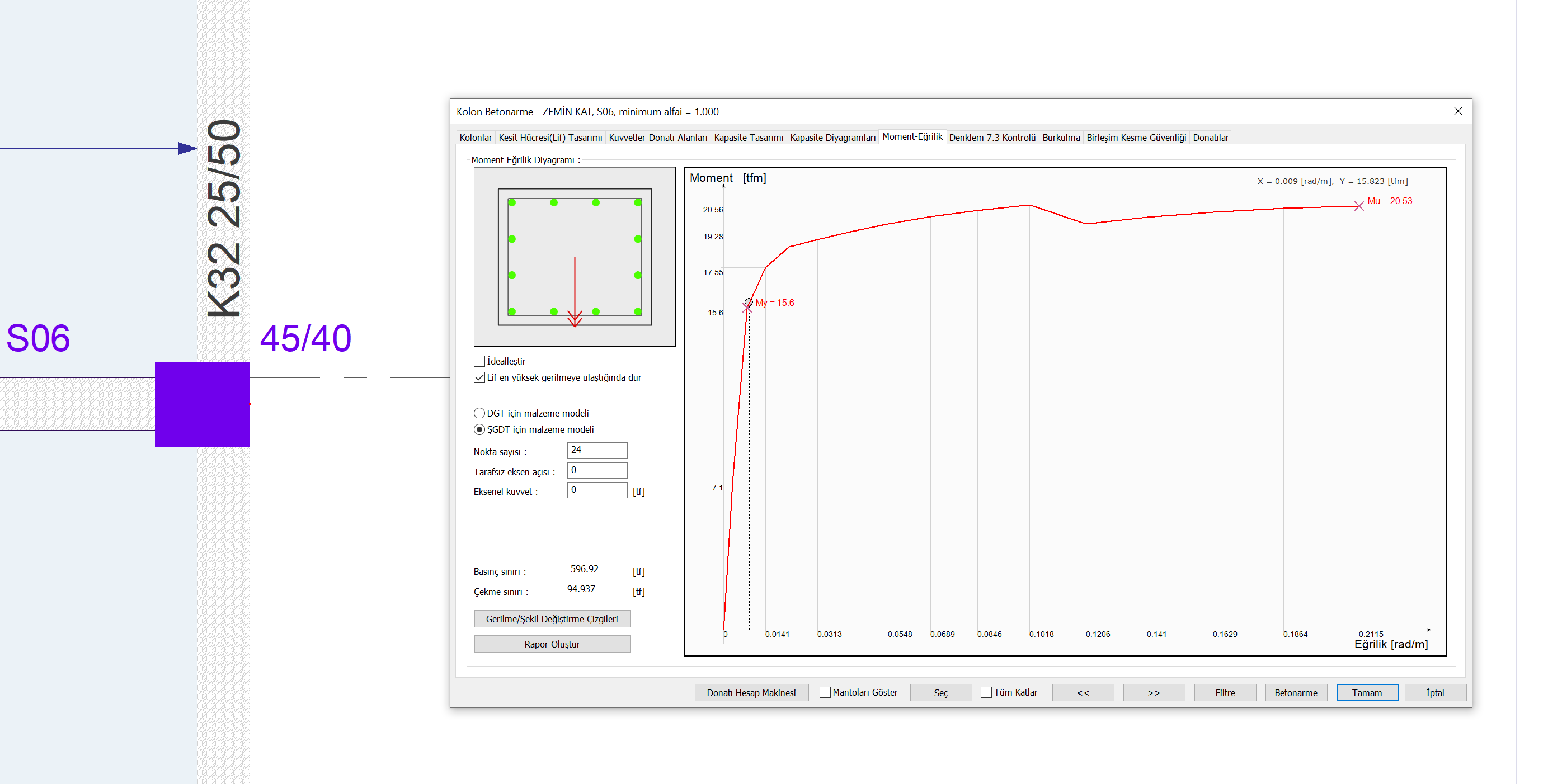
ECO values of ductile columns are taken into account in accordance with the earthquake direction. If the bending moment capacity is calculated for the earthquake direction in the column (X) marked with purple in the picture below, the bending moment strength will be the moment strength around the 3 axis (the vector shown with the red arrow in the picture below). (X) creates a bending moment effect around the earthquake direction 3 axis. If the bending moment value around the 3 axis, consisting of the earthquake loads in the (X) direction, taken as vertical loads and R a = 1, is divided by the bending moment strength around the 3 axis, the ECO value for this internal force is found. The EKO value is then scaled by the shear force. EKO scaled with shear force after these operations for all columns values are averaged and it is checked whether it is greater than 3.
(e) The average ECO values of ductile beams in the direction of the earthquake (X) and (Y) in any floor of the building other than the upper floor is greater than 5.
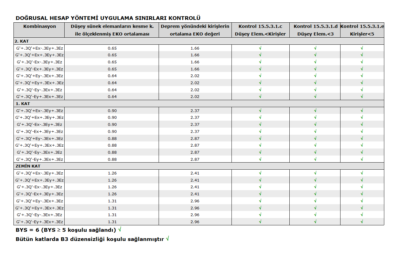
The ECO value is the ratio of the internal force value consisting of vertical loads and earthquake loads ( loading conditions ) taken as R a = 1 to the cross-sectional capacity calculated by considering the Knowledge Level Coefficient and Available Material Strengths . Therefore, ECO values depend on the reinforcement placement of the sections, material strength and internal strength value. In order for the ECO value used in the control of the application limits of linear calculation methods to be calculated correctly, the reinforcement placement, material strength and information level coefficient of the existing structure must be selected correctly. An example of TBDY 15.5.3.1 Linear Calculation Method Application Limits Control report is shown in the sample report below.
Next Topic
Related Topics