Modeling of Shearwalls per ASCE 7-16 with ideCAD
How ideCAD makes Shearwall modeling according to ASCE 7-16?
Rectangular reinforced concrete shearwalls are structural system elements defined according to ACI 318-19 Table R18.10.1. In the geometry control and the select report, the ratio of the length in the cross-section to its thickness is automatically checked, and a warning is given if there is an unsuitable situation for control.
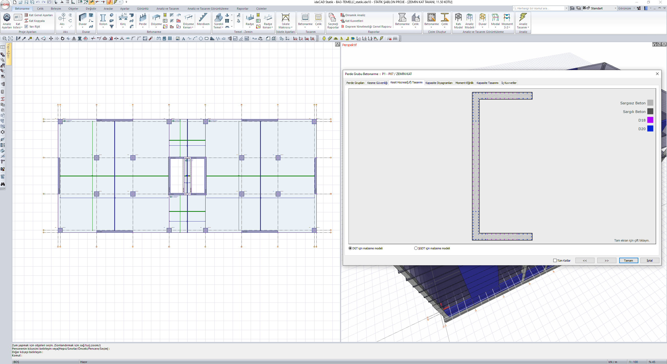
In reinforced concrete walls with cross-section shape I, T, L, U or C, the ratio of the length of at least one shearwall arm in each direction to its thickness should obey the rule. Otherwise, the structural system element will not be counted as a shearwall in that direction. If this condition is not met in the geometry control, a warning is given automatically and the error is listed on the first page of the reports.
Rectangular Reinforced Concrete Walls
Rectangular reinforced concrete shearwalls are structural system elements defined according to ACI 318-19 Table R18.10.1. In the geometry control and the select report, the ratio of the length in the cross-section to its thickness is automatically checked and a warning is given if there is an unsuitable situation for control.
Polygonal Shear Walls
In reinforced concrete walls with cross-section shape I, T, L, U or C, the ratio of the length of at least one shearwall arm in each direction to its thickness should obey the rule. Otherwise, the structural system element will not be counted as a shearwall in that direction. If this condition is not met in the geometry control, a warning is given automatically and the error is listed on the first page of the reports.

