
-
With the calculation method explained in 4.3.6.2 , if the user chooses, calculations are made automatically by using this calculation method.
-
With the calculation method with two loading status explained in 4.8.5.1 , 4.8.5.2 and 4.8.5.3 , if selected by the user, calculations are made automatically by using this calculation method.
Symbols
D = Resistance excess coefficient
D bottom = Resistance Redundancy applied to the lower part of the building Factor
D top = applied to the lower part of the building Resistance Redundancy Factor
I = building importance factor
R = Move the behavior factor
R sub = Move applied to the lower part of the building system behavior factor
R top = The carrier system behavior coefficient applied to the upper part of the building
( R a ) sub = Earthquake Load Reduction Coefficient applied to the lower part of the building
It is the two-stage analysis method mentioned in 4.8.5 . According to the method, the lower section, rigid basement floors, and the upper section are analyzed for two different situations in one model and the results are combined.
In the upper section analysis, the entire building model is created, but the lower section mass is not included. The mass and rigidity of the superstructure elements and the lower section elements are considered only with their rigidity. As a result of the analysis, internal force and displacements are obtained in both the upper section and the lower section. During the analysis, the R and D coefficients suitable for the carrier system should be selected from Table 4.1 for the upper section.
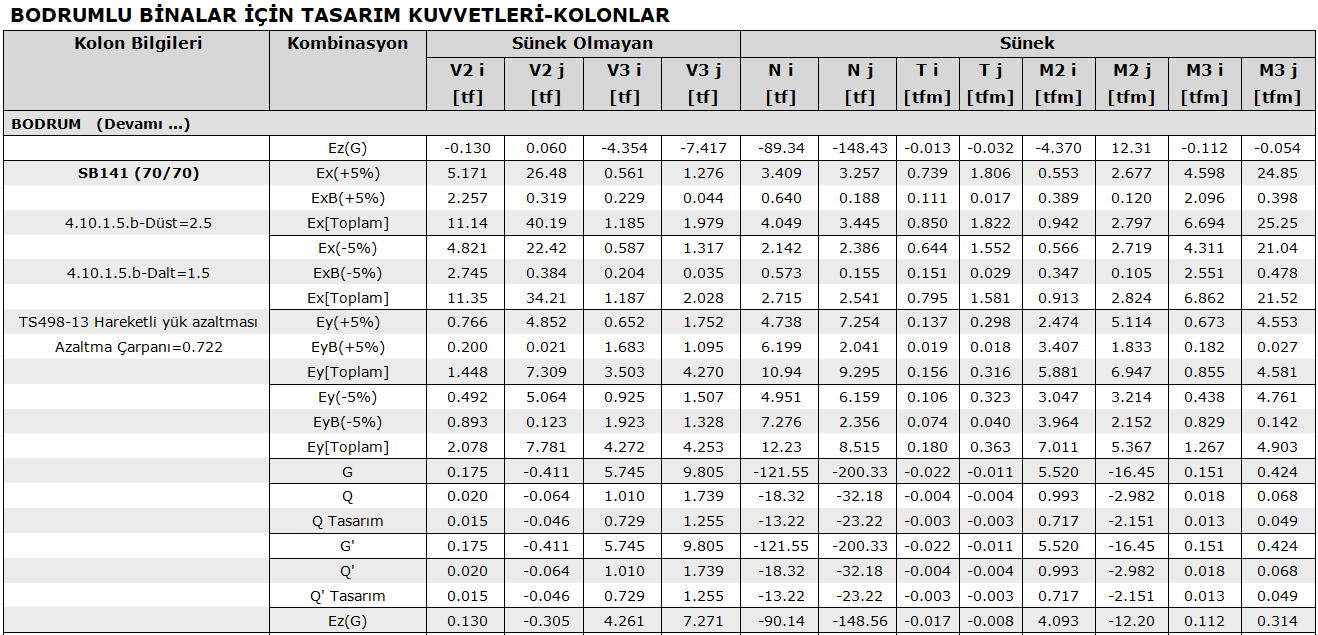
In the subsection analysis, the entire building model is created, but the upper section mass is not included in the calculation. Stiffness and mass of lower section elements are taken into account, while only stiffness of upper section elements are taken into account. For the sub section , operation is done with (R alt /I)=2.5 and D alt = 1.5. As a result of this analysis, internal forces and displacements in subdivision elements are obtained.
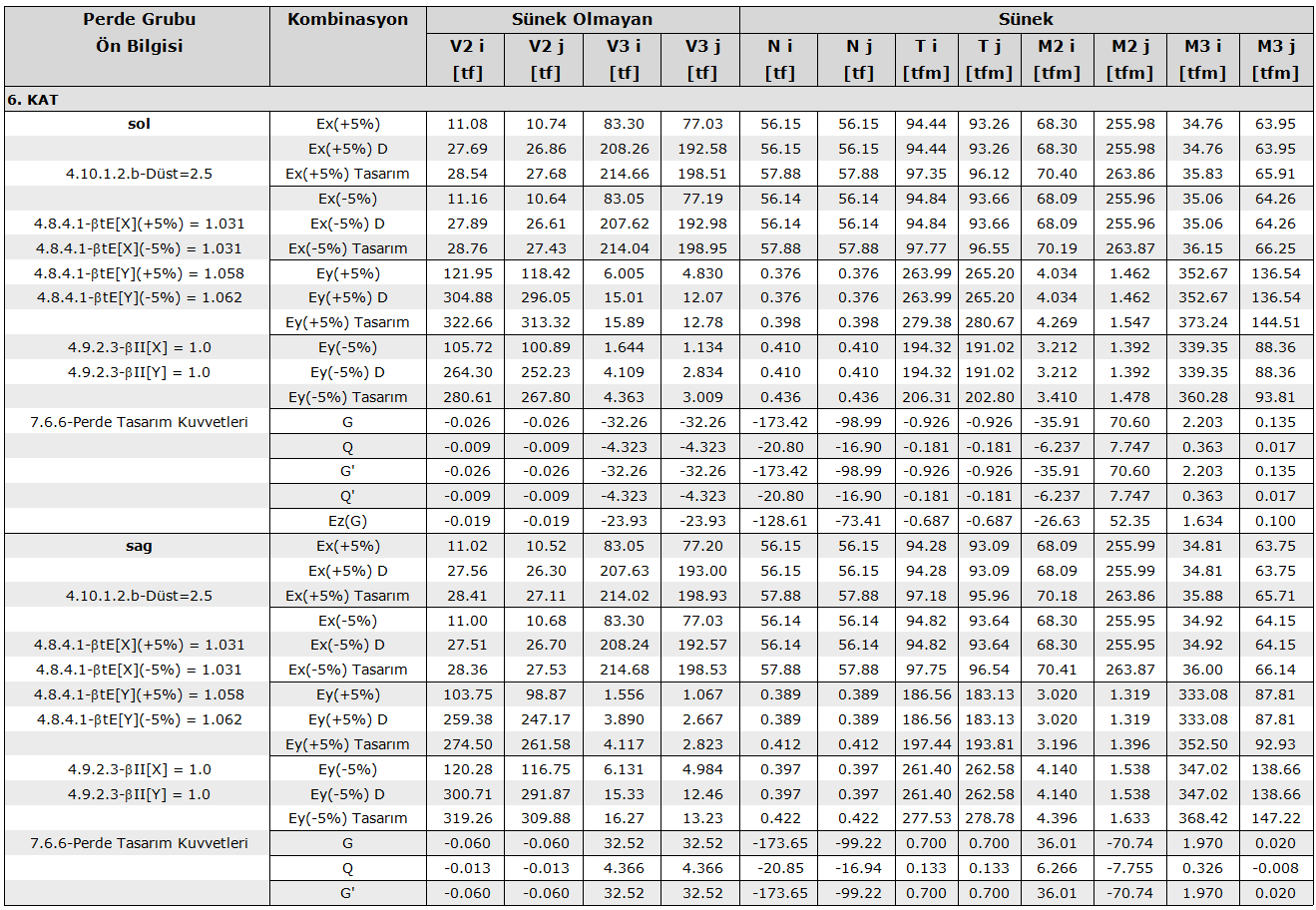
Top and Bottom Analysis Joining The results obtained after the analysis are combined in accordance with ductile and non-ductile internal forces according to TBDY 4.10.1 .
In the lower part, internal forces based on the design against ductile behavior; It is taken as the sum of internal forces obtained from the upper and lower section analyzes. The reason why the mode combination rules are not used here is that the maximum values of the behavior magnitudes calculated in the basement elements vibrating at very high frequencies in the lower loading condition and the maximum values of the behavior magnitudes calculated in the upper section elements vibrating at much lower frequencies in the upper loading state are the high probability of coincidence in time environment due to these frequency differences.
In the lower part, the internal forces based on the design against the non-ductile behavior; the internal forces are obtained in the case of the second installation D received multiplied by the top of the internal forces are obtained in the lower part if the first loading 0.6DIt is obtained by adding the product of the top .
In the reports of reinforced concrete elements, in the part of internal forces based on design, the raw results for the upper section in basement structures according to the ductile and non-ductile conditions and the values obtained from both stages for the lower section are given with the values increased according to the ductile and non-ductile conditions.
Next Topic