
UBC 97: 1997 Uniform Building Code
UBC 97 refers to the 1997 Uniform Building Code, one of the world's most widely used model building codes.
Download ideCAD for Seismic Code Design with UBC 97
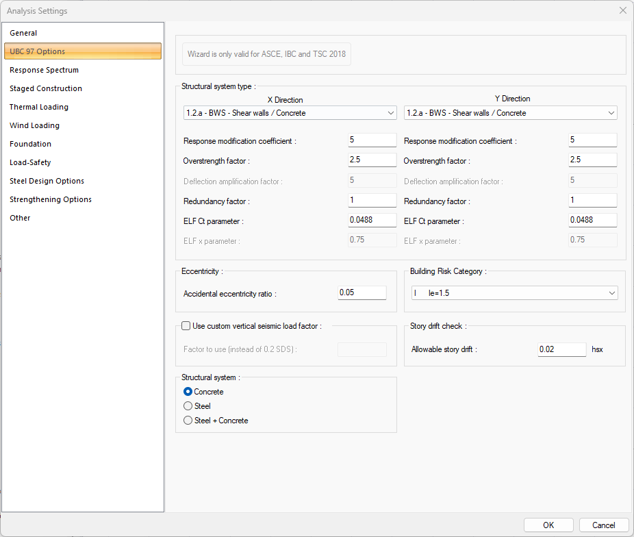
Analysis settings that vary depending on the UBC 97 are explained in detail.
UBC 97 Options Tab in ideCAD Structural
|
Specifications |
|---|
|
Structural system type 
The type of structural system for X and Y direction is selected in accordance with the design of the building. |
|
Response modification coefficient It is the response modification coefficient value. This row is automatically refreshed when the structural system type is chosen. |
|
Overstrength factor It is the strength excess coefficient value. This row is automatically refreshed when the structural system type is chosen. |
|
Redundancy factor It is the redundancy factor value. This row is automatically refreshed when the structural system type is chosen. |
|
ELF Ct parameter It is the ELF Ct parameter. This row is automatically refreshed when the structural system type is chosen. |
|
Accidental eccentricity ratio 
The eccentricity ratio to be used during the analysis is given as a percentage. |
|
Use custom vertical seismic load factor 
If checked, the custom vertical seismic load factor which entered in "factor to use (instead of 0.2 SDS)" line is used. |
|
Structural system 
If the building block consists of only concrete elements, Concrete; if it consists of only steel elements, Steel; Steel + Concrete option is selected if it consists of concrete and steel elements. |
|
Building Risk Category 
Building risk category value is selected from the list according to the purpose of use of the building. |
|
Story drift check 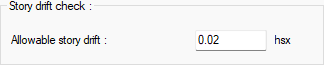
Allowable story drift value is entered. |
Response Spectrum Tab
|
Specifications |
|---|
|
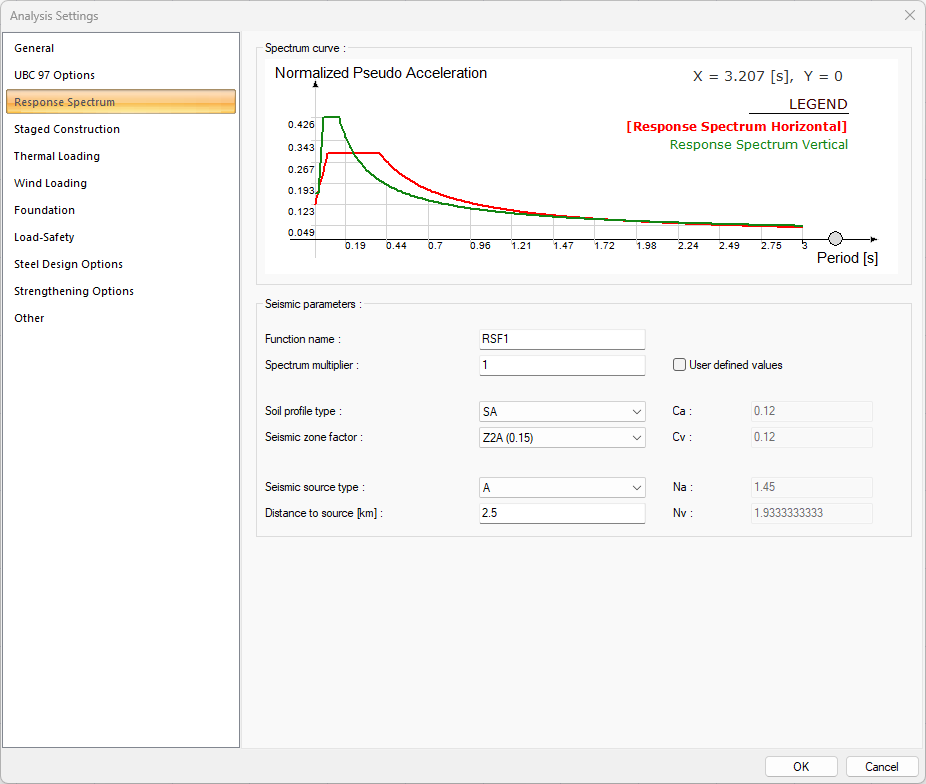
Spectrum curve 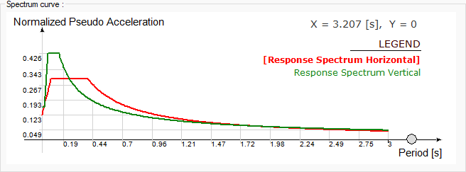
The spectrum curve resulting from the settings is shown. |
|
Function name The name of the spectrum function. |
|
Spectrum multiplier Factor of spectrum function. |
|
Soil profile type Soil profile type is selected for the response spectrum. |
|
Seismic zone factor Seismic zone factor value is entered for the response spectrum. |
|
Seismic source type Seismic source type is selected for the response spectrum. |
|
Distance to source [km] Distance to source value is entered for the response spectrum. |
|
User defined values If this option is selected, parameters such as Ca, Cv, Na and Nv become active. |
|
Ca/Cv 
Seismic coefficient value is entered for the response spectrum. |
|
Na Near source factor use in the detemination of Ca for the response spectrum. |
|
Nv Near source factor use in the detemination of Cv for the response spectrum. |
Download ideCAD for UBC 97
Next Topic
Related Topics