
Parameters and options for section/view drawings can be accessed with the Section Line Settings/Elevation Line Settings commands. Section/elevation settings are made according to the project.
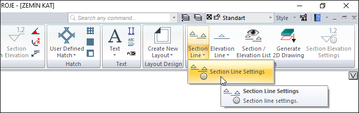
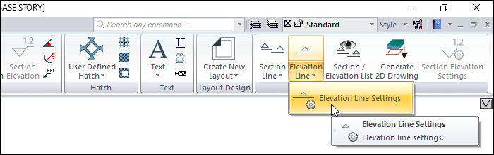
Location of the Section/Elevation Line Settings Command
You can access Section Line Settings and Elevation Line Settings from the ribbon menu Drawings tab Tools heading .
Also you can access section/elevation line settings from the section toolbar. If you click the settings icon while in the section command, the section settings will open, if you click the settings icon in the elevation command, the elevation settings will open.
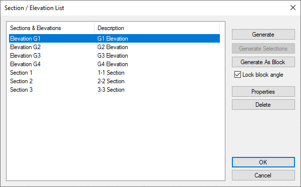
In addition, by clicking the properties button from the section/elevation list, you can access the settings of the selected section/elevation line from the list.
By double clicking on the drawn section/elevation line with the left mouse button, you can access the settings of that section/elevation.
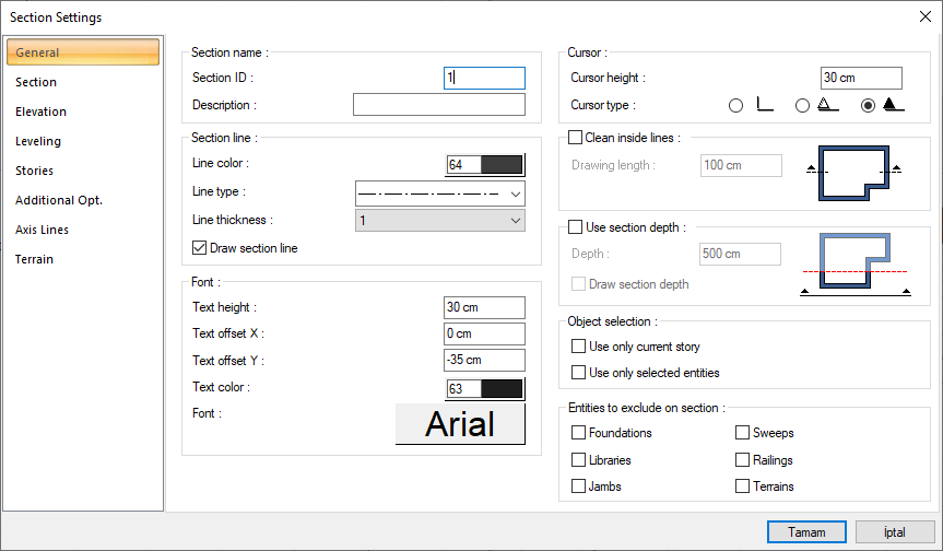
General Tab
|
Specifications |
|---|
|
Section ID/Elevation ID It is the name of the section or elevation line shown in the plan. |
|
Description It is the description written under the section or elevation drawing. If the description line is left blank, an automatic definition is created with the name written in the section/elevation ıd line. |
|
Line color The color of the line of the section or elevation line in the plan. You can choose the appropriate color from the color palette that opens when the color box is clicked. |
|
Line type It is the line type of the line of the section or elevation line in the plan. You can select a suitable type by clicking the linetype list. |
|
Line thickness It is the line thickness of the line of the section or elevation line visible in the plan. When the down arrow button next to the box is clicked, the appropriate thickness is selected from the drop-down list. The thickness selected here is only valid on the screen. It does not affect the drawing printouts. |
|
Draw section line If option is selected, section or elevation line is shown in plan. If the option is unchecked, the line itself is not shown in the drawing plan. You can open the section/elevation settings dialog from the Section/Elevation List command to make the line visible again. |
|
Text height It is the text height of the section/elevation ıd text written at the beginning and end of the section or elevation line. |
|
Text offset X/Y It is the distance from the section or elevation line of the section/elevation ıd text written at the beginning and end of the section or elevation line. |
|
Text color It is the color of the section/elevation ıd text written at the beginning and end of the section or elevation line. The color palette is opened by clicking the box and a color is selected from the list. |
|
Font The font of the section or elevation ıd text written at the beginning and end of the section or elevation line. The font dialog opens by clicking the font box. The appropriate font is selected in the dialog. |
|
Height It is the size of the direction sign placed at the beginning and end of the section or elevation line. |
|
Cursor type The type of direction cursor placed at the start and end of the section or elevation line. |
|
Clean inside lines and drwaing length 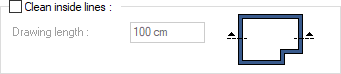
This option regulates whether the portion of the section or elevation line that falls within the structure contour is drawn. If the option is not selected, the section and elevation line are also shown within the building contour. If the option is selected, the section/elevation line can only be shown in the structure contour as much as the line length value. |
|
Consider the section depth 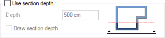
With this option, a depth is determined parallel to the section / view line and only the section / view of that area is taken. |
|
Object selection 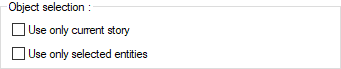
Only the active story or selected objects can be sectioned by selecting one of the options. |
|
Entities to exclude on section 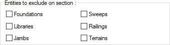
The marked of foundations, libraries, jambs, sweeps, railings and terrains are not cut. |
Section Tab
|
Specifications |
|---|
|
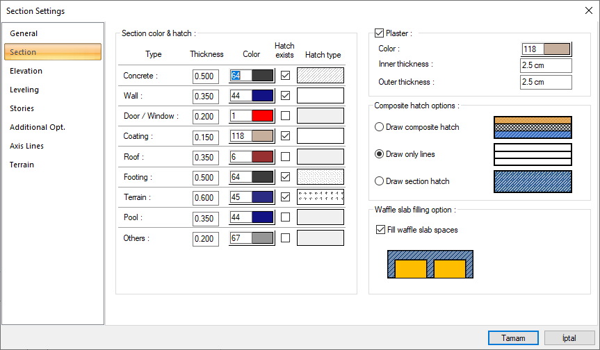
Cut object color and scan settings In this dialog, the colors, hatching types and thickness values of the cut objects are set. The cut objects are divided into different object types such as concrete, wall, door/window, coating, roof, footing, terrain, pool and other, and thickness, color and hatching type can be arranged for each type. |
|
Type 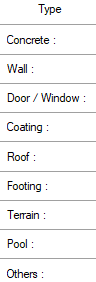
The list of objects that fall into the section, divided into types. |
|
Thickness The pen thickness that will appear in the section of the cut objects is listed. The thickness value of the assigned color is displayed on the thickness line. |
|
Color 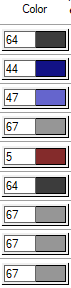
The colors of the cut object can be adjusted according to the object type. A color is selected by clicking the color box. The pen thickness of the color is determined by clicking the right mouse button on the color box. |
|
Hatch exists If the option is checked, it means that the cut object will be hatched. If the option is not selected, it means the object will be left blank without hatching. |
|
Hatch type 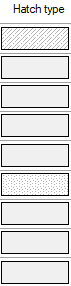
Hatch type of the object is set. Clicking on hatch opens the Hatch Settings dialog. The hatch type is selected from the lookup table in this dialog. |
|
Plaster It is the option that determines whether there will be plaster on the objects in the section. |
|
Color The color of the plaster to be shown in the section. A color can be selected from the color palette by clicking the color box. |
|
Inner thickness It is the thickness of the plaster remaining inside the building. |
|
Outer thickness It is the thickness of the plaster remaining on the exterior of the building. |
|
Composite hatch options In order for this option to be active, the option on the right side of the dialog must be checked. |
|
Draw composite hatch Composite materials assigned in the section's own settings of the entities become active and the entities are hatched with their composite material. |
|
Draw only lines Hatches of composite materials assigned in the section's own settings of entities are not drawn, only layer lines are drawn. |
|
Draw section hatch The hatch type on the right side of the dialog becomes active and entities in the section are hatched with the selected hatch type. |
|
Fill waffle slab spaces 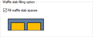
In ribbed slab, it regulates whether the gap between the teeth will be closed in the section. If the option is selected, the lines between the ribs are closed. |
Elevation Tab
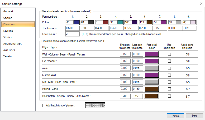
Objects that appear in sections and elevation can be drawn in different colors and with different thicknesses by separating them into different level groups as they move away from the vertical section and elevation plane, by defining different color and pen number as object and object groups at each different level. The number of levels, pen thicknesses and colors can be edited by the user in the project.
|
Specifications |
|---|
|
Elevation levels pen list 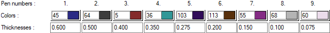
In the pen list created from 1 to 9, color and pen thickness are adjusted according to item numbers. The colors and thicknesses of the objects that are apparently leveled and pen thicknesses are determined depending on the color indexes. Colors are selected from the color pack opened by holding down the left mouse button. Objects that enter the leveling are drawn according to the selected colors. In the drawing phase, pen thicknesses are taken into consideration. |
|
Level count The number of items to be assigned to the levels considered in vertical section and elevation. The colors to be applied in the levels are determined according to the value entered in this row. For example, in a view with 3 different levels, if the level number 5 is entered, the 1st level will be the 1st color; 2nd level with 2nd color; Level 3 with color 3; Level 4 with color 4; Level 5 is drawn in color 5. If level number 3 is entered, level 1 will be transferred with 1st color; 2nd level with 2nd color; Levels 3, 4 and 5 are drawn in third color. If the level number is 1, all levels are drawn in 1st color. |
|
Object types 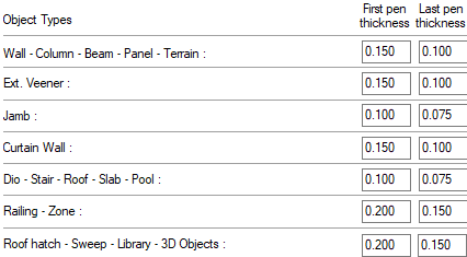
Elements to be seen can be drawn in different colors and pens according to a certain level, and in addition, objects at the same level are divided into types and different color and pen thickness can be arranged for them. Object types are specified as shown in the list, and different pen thicknesses can be applied by giving them the initial and final pen thickness. |
|
Use single pen and First level color 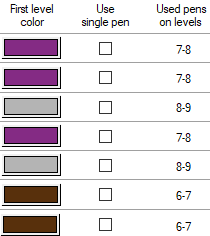
If this option is selected, the pen thickness to be used for the relevant object type will be the same as the pen thickness of the color given in the first level color. If the option is not selected, the pen thickness range is taken into account as much as the number of items given in the number of levels row, based on the thickness of the color selected in the first level color box. For example, for Jamb, the first level color should be given the same as the color selected in the 1st pen number. The number of levels, for example, is 3. If the Use one pen option is selected, the jamb pen thickness will be taken as the thickness value given for the 1st pen. If the single pen is not marked, the pen thickness values given for item numbers 1, 2, and 3, respectively, will be used. Item thicknesses to be used in levels are also shown in the column used in Levels. |
|
Add hatch to roof planes The option that determines whether roofs can be hatched in appearance. If the option is selected, the frame is hatched according to the hatch type selected in the search box. |
Leveling Tab
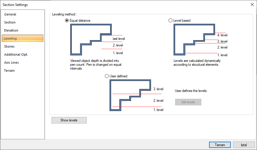
Objects that appear in sections and elevation can be drawn in different colors and with different pen thicknesses by separating them into different level groups as they move away from the section and elevation plane, by defining different color and pen number as object and object groups at each different level. In this dialog, the method to be used for leveling is determined.
|
Options and Descriptions |
|
Equal distance 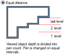
The depth of the visible object is divided by the number of pens given in the view tab, the color and pen thickness change in seemingly equal intervals. |
|
Level based 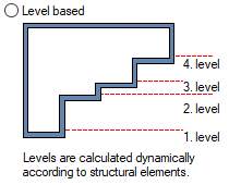
Levels are calculated automatically by looking at the positions of the existing building elements close to or far from the section or elevation line. |
|
User defined 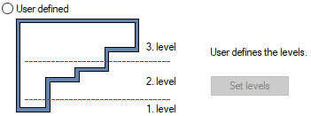
Levels are determined by the user by marking on the project by clicking on the Set Levels button. |
|
Show levels The user is shown with a preview where the levels have passed. |
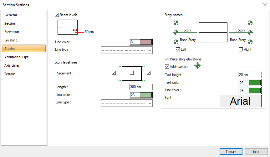
Stories Tab
|
Specifications - Beam levels |
|
Beam levels 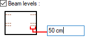
It is the option that determines whether to show beam traces in section and elevation. If the option is checked, the beams are shown visually according to the given length value. |
|
Line color The color of the beam trace to be drawn in sight. A color is selected from the color palette that is opened by clicking the color box. |
|
Line type It is the type of line of the beam trace that will apparently be drawn. An appropriate type is selected from the line type list. |
|
Specifications - Story level lines |
|---|
|
Placement Story level lines are shown visually, depending on the selection. |
|
Length It determines how long story level lines will be drawn out of the section or elevation plane. |
|
Line color It is the color of story level lines. A color is selected from the color palette that is opened by clicking the color box. |
|
Line type It is the line type of story level lines. An appropriate type is selected from the line type list. |
|
Specifications - Story names |
|
Layout layout - Left / Right 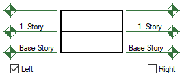
Writes the story names to the left and/or right of the section or elevation plane. |
|
Write story elevations On the story lines, it shows the story heights in parallel with the number of stories, with their total value. |
|
Add markers Adds elevation mark above story lines. |
|
Text height It is the font height of the writing of the story names. The larger the value, the larger the text size. |
|
Text color It is the font color of the story names writing. A color is selected from the color palette that is opened by clicking the color box. |
|
Line color The color of the story alignment lines. A color is selected from the color palette that is opened by clicking the color box. |
|
Font The font of the story names text. |
Additional Options Tab
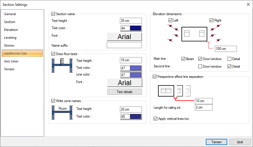
|
Specifications - Section name |
|
Section name The name of the section or elevation is written under the section or elevation drawing. |
|
Text height The text height of the section/elevation name text. |
|
Text color The color of the section/elevation name text. When the color box is clicked, the appropriate color is selected from the window that opens. |
|
Font The font of the section or elevation name text is selected. |
|
Name suffix It is the text that is requested to be written after the section/elevation name text. |
|
Specifications - Draw Floor Texts |
|---|
|
Draw floor texts 
It shows the floor material list of the drawn elements in section. The floor material list can be prepared by clicking the text details dialog below. |
|
Text height It is the writing height of material text. |
|
Text color
It is the font color of material writings. |
|
Line color It is the text color of material text. |
|
Font It is the text of material writings. |
|
Text details This is the section where the material list is arranged. When the button is clicked , a dialog called Text Details opens. In the dialog, text can be entered for concrete, zone coating, ribbed and waffle slab, waffle filling, plaster, hole. The entered texts are shown by removing the arrows for the relevant element in the section. 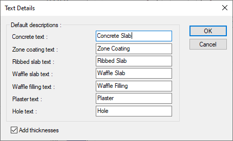
Add thickness: In addition to the section text, the element thickness is added automatically (such as plaster 2.5 cm). |
|
Specifications - Write Zone Names |
|
Write Zone Names 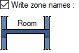
It shows the names of the zones in their respective positions in the section. The zone names can be arranged for the zones defined in the section settings. |
|
Text height It is the text height of the zone name. |
|
Text color It is the text color of the zone name. |
|
Specifications - Elevation Dimensions |
|
Elevation Dimensions - Left / Right 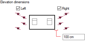
Writes the elevation measurements on the left and/or right of the section or elevation plane. Level dimensions are created according to the entered distance value. |
|
Main line Sets the level of the 1st line for beam, door/window and details. |
|
Second line For the door/window and details, it arranges the level of the 2nd line in the summer of the 1st line. |
|
Specifications - Perspective Effect Line Seperation |
|
Perspective effect line seperation 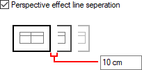
Adjusts whether or not consecutive object lines touch each other in section and elevation by the entered length value. |
|
Length for railing int. The option is reserved for handrails. Give the distance value. |
|
Apply vertical lines too Perspective effect is applied for section and elevation lines drawn in vertical direction. |
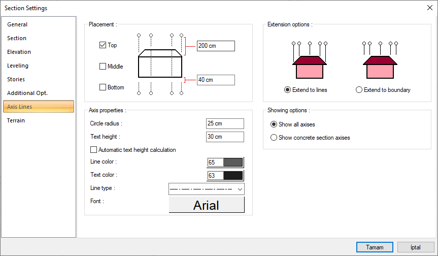
Axis Lines Tab
|
Specifications |
|---|
|
Placement 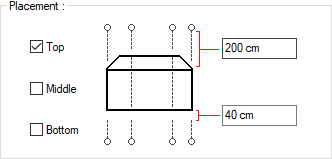
Where the axes in the section/elevation plane will be shown in the drawing are determined by marking the desired options from the top, middle and the bottom options. The distance of the axes from the drawing and the values for the axes lengths are entered in the boxes in the schematic drawing. |
|
Circle radius It is the radius value that determines the size of the axis circles shown in the section/elevation drawing. |
|
Text height It is the value determining the text size of the axis names shown in the section/elevation drawing. |
|
Automatic text height calculation If the automatic text height is marked, the size of the axis names is determined automatically according to the size of the axis circle, the given text height is not taken into account. |
|
Line color Determines the color of the axis lines. You can choose another color from the color dialog that opens when clicked. |
|
Text color It determines the color of the axis text. You can choose another color from the color dialog that opens when clicked. |
|
Line type Determines the line type of axis lines. Clicking on the drop-down list can choose another type. |
|
Font Determines the font of the axes text. Clicking on the drop-down list can choose another type. |
|
Extend to lines 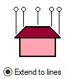
All axises are roof or wall etc. It is extended according to the form of the objects. |
|
Extend to boundary 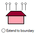
All axises are roof or wall etc. It is extended to an alignment with respect to the top point of objects. |
|
Show all axes Shows all axises that are within the section/elevation plane. |
|
Show concrete section axises Columns, beams and shearwall etc. within the section/elevation plane. shows the axes that pass over the elements and determine the concrete construction. |
Terrain Tab
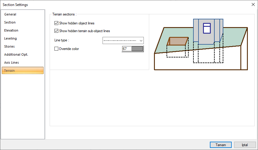
In section and elevation, it is the tab that determines the properties of the visible or hidden lines behind the terrain and the line types related to the section lines of the terrain object. Choose the options referring to the shape.
|
Specifications |
|
Show hidden object lines 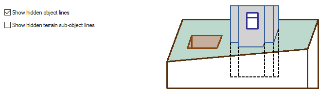
Draws the lines of objects behind the terrain with the selected line type in the section or elevation. |
|
Show hidden terrain sub-object lines 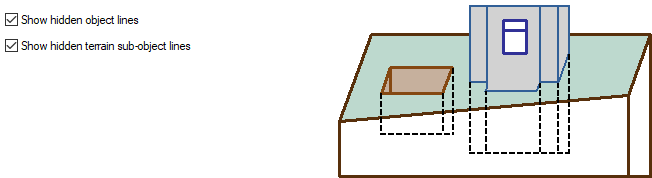
Draws the terrain lines behind the terrain object in section and elevation with the selected line type. |
|
Line type The line type of the hidden lines is selected from the list. |
|
Override color If the option is checked, hidden lines will be drawn in the chosen color. |
Next Topic