
Edits are made for existing stairs with the Stairs Edit command. The properties of the stairs to be edited are entered. Parameters such as stair width, length, height, construction type, material, railing and handrail types are included in the stair edit dialog.
Location of the Stair Edit Command
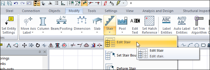
You can access it under the ribbon menu Modify tab, Stair title.
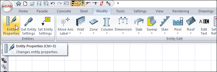
Also you can access the Stair Edit dialog by clicking the Modify tab, Entity Properties title after select the object to edit.
Parameters-2D View Tab

|
Specifications |
|---|
|
Stair flight width The stair flight width is determined. |
|
Stair flight length The stair flight length is determined. |
|
Landing width The landing width is determined. |
|
Landing length The landing length is determined. |
|
Landing elevation The elevation of the landing from the ground is determined. |
|
Railing distance The distance of the railing to the edge of the stairs is determined. |
|
Railing thickness Railing thickness is determined. |
|
Stair thickness The thickness of the stair plate is determined. |
|
Stair height The height of the stair is determined. |
|
Railing height The height of the railing is determined. |
|
Line of travel offset distance How far the line of travel will be from the outer edge of the stair is determined. |
|
Line of travel circle radius The line of travel circle radius is determined. |
|
Line of travel arrow length The line of travel arrow length is determined. |
|
2D view 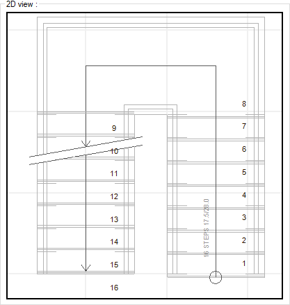
There is a 2D plan view of the stair. Changes made in parameters are simultaneously reflected in the 2D view. |
Note
The parameters displayed in the Parameters-2D display tab may vary according to the stair type.
3D View Tab
|
Specifications |
|---|
|
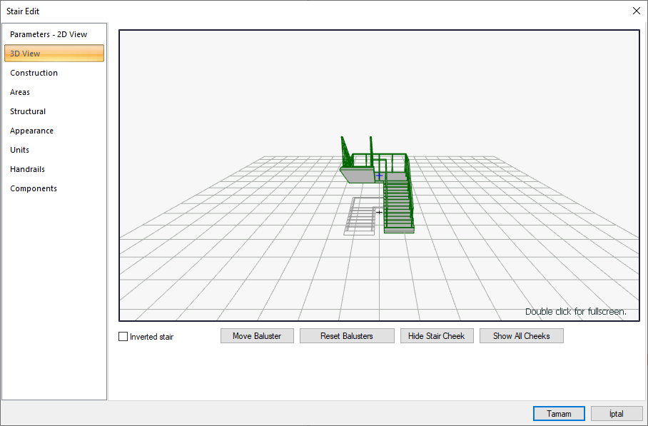
Preview 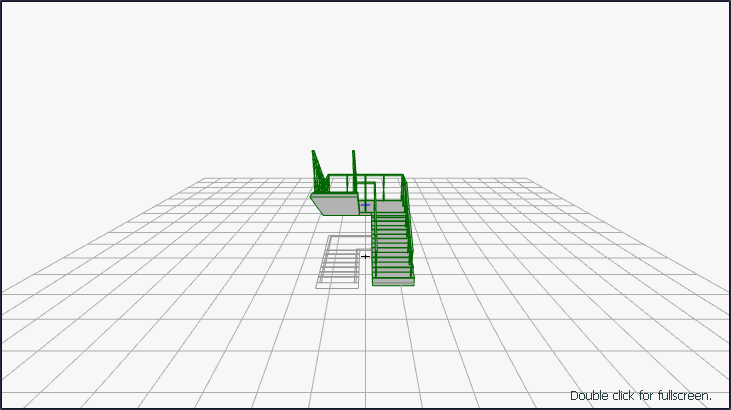
There is a three-dimensional view of the selected staircase. It is possible to zoom in, zoom out, rotate the 3D image. In this way, the properties of the stairs can be examined in three dimensions. |
|
Inverted stair It changes the exit direction of the stair flight. For example, a stair going from left to right makes a stair from right to left. |
|
Move baluster Place the mouse cursor on the railing that you want to move on the 3D stair model. The mouse is moved by clicking and holding down the left mouse button. It is seen that the related baluster also moves with the mouse. When the baluster is brought to the wanted position, the left button is released. |
|
Reset balusters The balusters, which were replaced with the move baluster command, bring them back to their original places. |
|
Hide stair cheek It may be desirable not to scratch any cheeks on cheek stairs. In this case, this button is clicked to remove the relevant cheeks. When the corresponding cheek is clicked with the left mouse button, the cheek is lifted (hidden). |
|
Show all cheeks Click this button if you want to show the hidden cheeks again. |
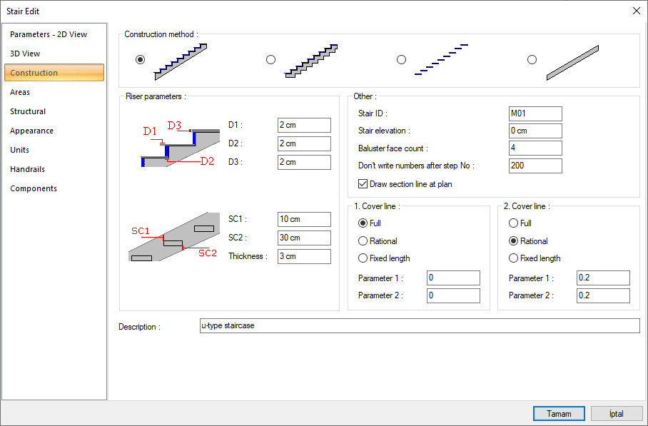
Construction Tab
|
Specifications |
|---|
|
Construction method 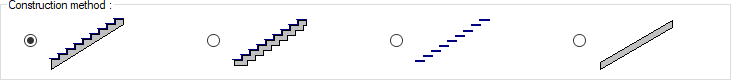
One of the straight, folded, bridge board and ramp type stair systems is selected by clicking with the left mouse button. |
|
Riser parameters 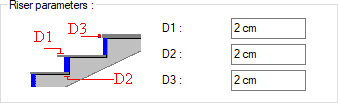
D1 is the step covering nose length, D2 is the riser covering thickness, D3 is the step covering thickness. If covering is not wanted, these values are entered as zero. |
|
Stair cheek parameters 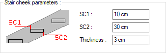
LK1 and LK2 determine the bridge board height. It is shown on the figure. The thickness parameter is the bridge board thickness. |
|
Stair ID The name of the stair is entered. |
|
Stair elevation The lower point of the stairs is the elevation measured from the floor base. |
|
Baluster face count The number of baluster surfaces determines the count of railing vertical surfaces (railing section). If the count of baluster surfaces is 4, the parapet cross section becomes square. |
|
Don’t write step numbers after The digits after the digit number entered here are not numbered on the stair. |
|
Draw section line If it is wanted to draw a section line on the stair, it is marked. |
|
1st and 2nd cover line 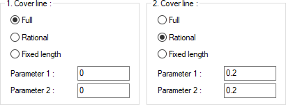
These are the parameters that determine how the lines showing the coatings on the stair will be drawn in the plan. Par1 and Par2 are the lengths of the pavement lines on the right and left sides of the stair. If the full option is selected, the cover line is drawn from one side of the stair to the other. If Proportional is selected, it is drawn according to the ratio of the entered Parameter 1 and Parameter 2 lengths to the stair width. If fixed length is selected, it is drawn as the length of Parameter 1 and Parameter 2. |
|
Definition The stair is the definition line. Replaceable. However, it does not have any effect on the stair. Only the definition has changed. |
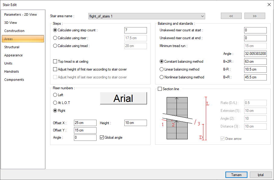
Areas Tab
|
Specifications |
|---|
|
Stairs area name When the down arrow button on the right of the box is clicked, the area list opens. Each area here represents a stair flight. If the stair consists of a single flight, there is only one flight in the list. The parameters here are set separately for each stair flight (area). |
|
Calculate using step count The required count of steps for the relevant area (stair flight) is entered in the right box. The flight length and height are specified and the step width and riser height are automatically calculated according to the entered number and written in the relevant boxes. |
|
Calculate using riser The required riser height is entered in the box to the right. The entered riser height is kept constant. The step width and the number of digits are automatically calculated depending on the entered digit height and written in the relevant boxes. |
|
Calculate using tread The wanted step width is entered in the box to the right. In this case, by keeping the step width constant, the riser height and the count of steps are automatically calculated according to this value and written in the relevant boxes. |
|
Top tread is at ceiling If this option is checked, the count of risers will be as much as the value of the determining parameter. For example; If the number of steps determining parameter is 7, there will be 7 berths on the related branch. This means that the number of digits is 6. There is also the 7th step, but this step is at the floor level where the landing or staircase meets. If the option is not checked, the number of risers, the number of steps is one more than the determining parameter value. That is, if the number of steps is 7, there will be 8 berths on the relevant branch. In this case, the number of digits will also be 7. The last step will be below the landing by one pier height. |
|
Adjust height of first/last riser according to the stair cover If covering is used on the stair, the appropriate option is selected to adjust the riser heights by taking the covering thickness into consideration. Height adjustment according to the cover can be made in the first step on some flights and on the last step on some flights. |
|
Unskewed riser count at start The step where the balancing will begin on the rotating stairs is determined here. For example; If 2 is entered, no offset is made for the two initial digits. From the third step, balancing (rotating steps) is started. |
|
Unskewed riser count at end It is the parameter that determines at which step the balancing (rotating steps) will end in rotating stairs. For example; If 2 is entered, balancing ends at the third from the last step. No balancing is made for the last two digits. |
|
Minimum tread run While balancing, how much the minimum step width can be is entered in this box. It can be intervened if the nonlinear balancing method is chosen. User cannot interfere when fixed and linear balancing methods are selected. |
|
Angle It is the slope of the stair. It is automatically calculated and written in this box. The user cannot intervene. Stair flight length and height vary depending on the step and the dock. |
|
Constant balancing method B+2R Refers to the stride length. Here B represents the step width, R stands for the height of the riser. Automatically changes when B or R changes. |
|
Linear balancing method B-R Refers to comfort. B is the step width, R is the riser height. Automatically changes when B or R changes. |
|
Nonlinear balancing method B+R Refers to security. B is the step width, R is the riser height. Automatically changes when B or R changes. |
|
Ricer numbers placement 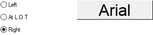
It is decided where the stair step numbers will be written by choosing one of the options of left, right or next to the line of travel arrow. The Font Settings dialog appears when the font button to the right of these options is clicked. From this dialog, the font and text effect are selected for the step writing. |
|
Offset X/Y X offset is used to shift the numbers horizontally and Y Offset vertically. Values can be positive or negative. |
|
Angle The angle of the step numbers are entered. When the angle is zero, the numbers are parallel to the steps. If the stair is turned, the writings also rotate with the stair. However, if the Global Angle option is selected, global angles are taken into account. Regardless of the angle of the stair, the angle of the posts will be the angle written here. |
|
Height Step is the height of the text. |
|
Section line If the box is checked, the section line is drawn on the relevant stair area (flight) according to the entered parameters. If not marked, the section line is not drawn. |
|
Section line diagram 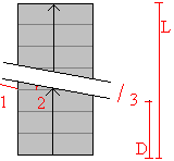
Sections of the section line are shown with schematic drawings and numbering. |
|
Ratio (D/L) It determines the location of the section line on the stair. |
|
Extension (1) It determines the distance of the section line to the outside of the stair. |
|
Angle (2) Determines the slope of the section line. |
|
Distance (3) Determines the distance between the section lines. |
|
Draw arrow If the box is checked, an arrow is drawn at the end of the line of origin on the section line. |
Structural Tab
|
Specifications |
|---|
|
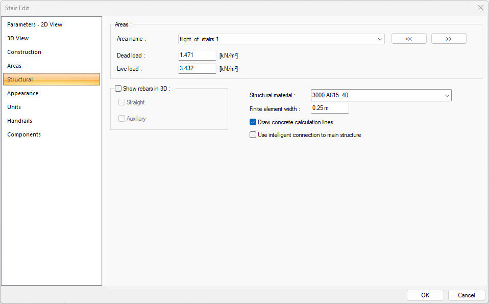
Area name The line where the name appears, indicating the stair area. Whichever flight we are in means we are changing the structural values of that flight. |
|
Dead load Fixed dead loads are entered, except for the reinforced concrete weight of the stair. |
|
Live load Live load value to be used in the stair calculation is entered. |
|
Show rebars in 3D 
It is the option that regulates whether the reinforcements calculated as a result of the stair analysis will be drawn in 3 dimensions, in the solid model image. Check the option if you want to see the reinforcement in 3D perspective. |
|
Structural material Select the structural material to be used in the stair element from the list. |
|
Finite element width Enter the maximum finite element width to be taken as basis in shell calculation. The ideCAD analyzes shells by dividing them into trapezoidal form finite elements. Finite element width is automatically adjusted according to the shell shape, provided that it does not exceed the value entered in this row. |
|
Draw concrete calculation lines If it is wanted to show reinforced concrete calculation axis, it is marked. |
|
Use intelligent connection to main structure The stairs are supported on the main structure with a smart connection. |
Appearance Tab
|
Specifications |
|---|
|
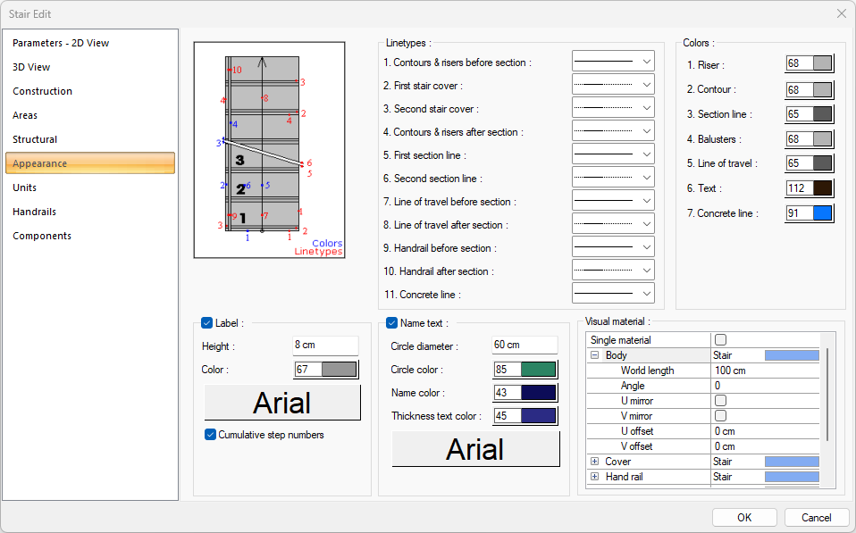
Schematic drawing 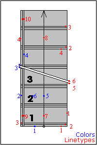
Which elements of the stair are defined by line types and colors are shown in schematic drawings and numbering. |
|
Linetypes 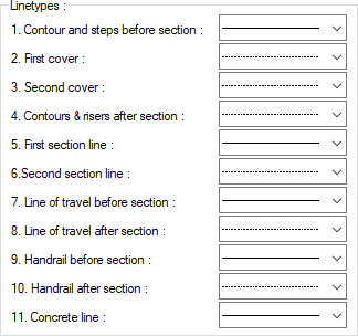
A separate line type is selected for the lines forming the stair in the plan. Clicking the down arrow buttons to the right of the boxes opens the list of line types. From this list, the wanted line type is selected by clicking with the left mouse button. The lines are numbered in red on the figure on the left. |
|
Colors 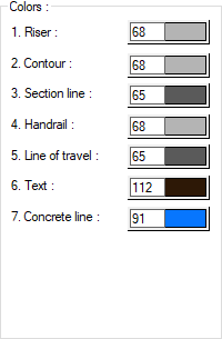
A separate color is chosen for the lines forming the stair in the plan. The lines are numbered in blue on the figure to the left of the dialog. When the color box is clicked, the appropriate color is selected from the window that opens. |
|
Label 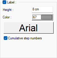
By marking the label, the number of risers, riser height and step width are shown on the stair. The font of the label font and the number of risers, the height and width of the digit is selected. The text color of the label color and the number of risers, the height and width of the digit is selected. The number of risers, the height of the digit and the height of the text of the width text are entered on the label height. The total number of digits is unmarked, and the number of risers, riser height and step width are shown separately on each branch. If checked, total values are shown. |
|
Name text 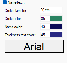
By marking the name text, stair name is shown on the stair. Circle diameter of the name text is entered. The font of the name text is selected. The text color of the circle, name and thickness text are selected. |
|
Visual material 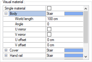
The material to be used on the body, cover, handrail and railing surfaces of the stairs is selected from the list. Surfaces are covered with the selected material and displayed as such in renderings. Texture length is entered into the world length. For example; If 1 is entered, the selected material texture is taken as 1 meter and covered on the relevant walls. The angle is the angle of the texture. In the U and V offset, the motion value in the x and y plane of the texture is entered. With U and V mirroring, the texture is symmetrical with respect to the y and x planes. By selecting the single material option, the material selected in the "Body" is used on all surfaces of the wall. |
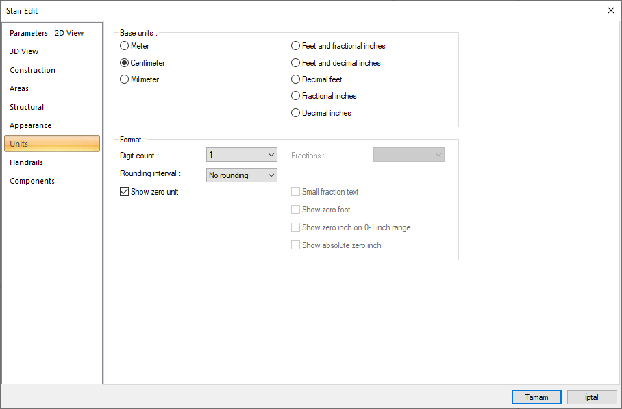
Units Tab
|
Specifications |
|---|
|
Basic units 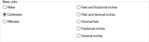
One of the selections is activated by clicking the left mouse button on the job. Meter : If checked, the unit of information text will be meters.
|
|
Digit count 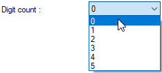
It determines how many digits will be shown after the comma. The desired number is selected from the list. For example, if 2 is selected, units will be shown as two digits after the comma. If 0 is selected, units will not be shown after the comma. |
|
Fractions 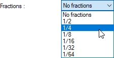
It determines the precision of the dimension to be made in fractional inch format. In the list, there are options with a sensitivity of 1/2, ¼, 1/8, 1/16, 1/32, 1/34. If "no fraction" is selected, units will appear without fractions. |
|
Rounding interval 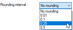
It determines the rounding range of the measurement to be made in meters, centimeters or millimeters. If No rounding is selected, the dimensioning is done at exact value. As the range gets larger, the dimensioning is rounded up to the selected range. |
|
Show zero unit If it is not checked, it does not show the zero and point on the left in dimensioning. For example, it measures 0.20 as 20. If marked, the value 0.20 is scaled as 0.20. |
|
Small fraction text When fractional inch format is selected, determines the fractional part to display in upper / lower case. If it is checked, the fraction is slightly above the integer and small, if not, the fraction is shown the same size next to the integer. |
|
Show zero foot Determines whether 0 is displayed in the 0-foot gauge (less than 1 foot gauge). For example, if it is not checked, it will show a measure of 0 '- 15 "as -15". If marked, it shows as 0'-15 ". |
|
Show zero inch on 0-1 inch range For example, a dimension inch with a value of 8'-0 1/6 "is in the range 0-1. If the option is not ticked, the value 8'-0 1/6" will be displayed as 8'-. In other words, inch values in the 0-1 range will not be displayed. |
|
Show absolute zero inch Determines whether to show zero inches in the dimension value where inches is absolute zero. For example, a dimension of exactly 10 'will be displayed as 10'-0 "if this option is selected. If not checked, it will be displayed as 10" -. |
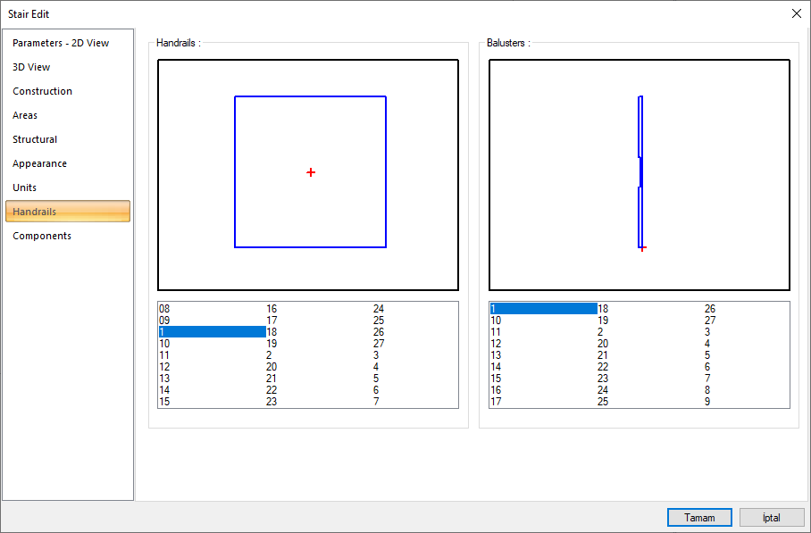
Handrail Tab
|
Specifications |
|---|
|
Handrail profiles 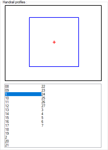
Select a handrail from the list of handrails by clicking with the left mouse button. The selected handrail section is displayed on the handrail screen. |
|
Baluster profiles 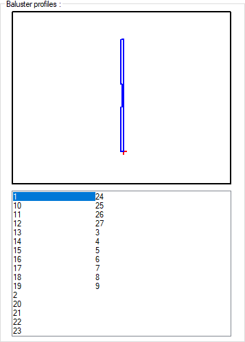
Select a baluster from the list of balusters by clicking the left mouse button. The selected baluster image is displayed on the baluster screen. |
Components Tab
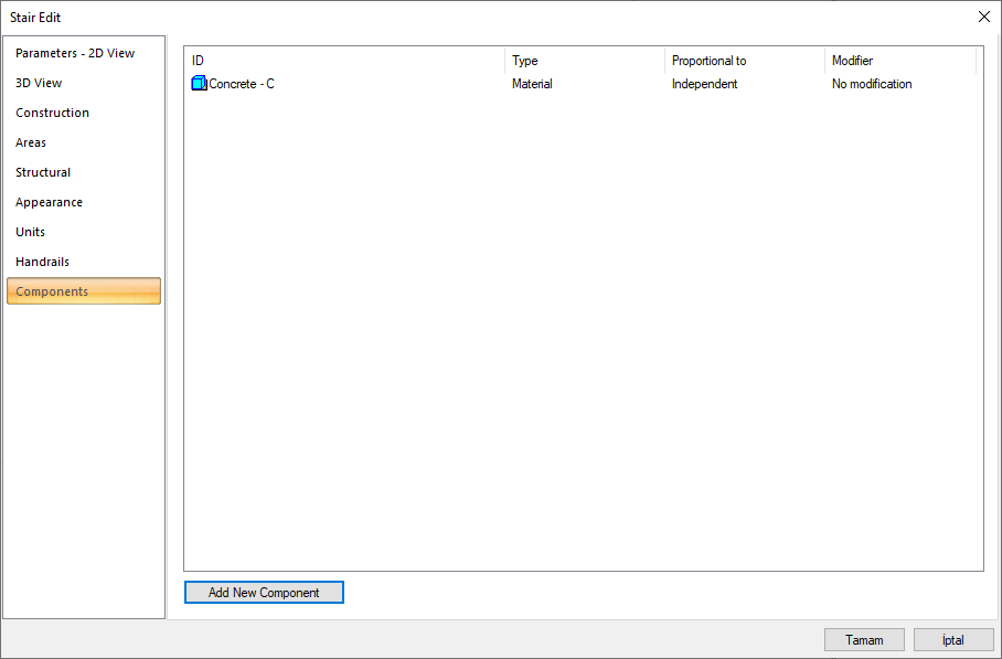
Add building components: Assigns the building materials defined for the detailed building components metering to the wall object.
-
Click the Add Building Component button.
-
The Component Selection dialog will open.
-
In this dialog, click the folder related to the material from the list on the left. Choose the material you want to use.
-
Set the parameters on the right.
-
Click the OK button. The "Component Selection" dialog will be closed. A summary line of the material will appear in the Building Components tab. More than one material assignment can be made to an object.
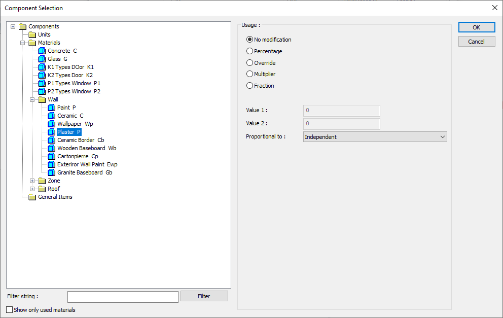
In the usage section
No modification: The amount of material to be assigned for the object in question is marked when it is desired to be used in the size that was previously specified in the material definition.
Percentage: This line is marked when it is desired to be used with the percentage of the amount previously determined in the material definition, as much as the value entered in the "Value 1" line in the same dialog. For example, if the material quantity is 70, if the line “Value 1” says 40, it means the material amount will be used up to 40 * 70%.
Override: This line is marked so that the quantity entered in the “Value 1” line in the same dialog will be used instead of the quantity previously determined in the material definition.
Multiplier: This line is marked in order to use the value found at the end of the multiplication of the value entered in the "Value 1" line in the same dialog with the amount previously determined in the material definition.
Fraction: This line is marked so that the amount determined in the material definition before will be used as the fraction value created by the values entered in the "Value 1" and "Value 2" lines in the same dialog. "Value 1" is the denominator "Value 2" is the denominator.
Proportional to: It is determined to what scale-area, circumference, length etc.-, region-side area, top, edge etc.- the material will be proportioned to. The content of the proportional list box is automatically determined according to the object and the size of the material. For example, a different list will be created if an operation is made for the column, a different list will be created for the library, a different list for the volume, and a different list for the field.
Following are the lines that appear in the proportion list according to the stair and material size.
|
Stairs |
||
|
Measure |
Listed |
Explanation |
|
Constant |
Independent |
The fixed measure used will be used exactly as the amount. |
|
Length |
Independent |
It means that the length measure found while defining the material will be used exactly as the length value. |
|
Line of the travel length |
It means that the length of the material will be found by multiplying the length measurement found when defining the material and the length of the exit line of the stair. |
|
|
Area |
Independent |
The area measure found when defining the material will be used exactly as the area of the material. |
|
Top area |
It means that the area measure found when defining the material will be multiplied by the area of the upper surface of the stair. |
|
|
Volume |
Independent |
The volume measure found when defining the material will be used exactly as the volume of the material. |
|
Count |
Independent |
The number measure found while defining the material will be used exactly as the material number. |
|
|
Count |
The number measure found while defining the material will be used exactly as the material number. |
|
|
Riser count |
It means that the number measure found when defining the material will be multiplied by the number of rises of the stair. |
Next Topic