
Insufficient conditions for raft foundation reinforcement design and raft foundations are displayed in the Slab Reinforcement dialog. In the Raft Foundation Reinforcement dialog, flat and additional reinforcement information used on the raft foundation is given.
Location of Slab (Raft Foundation) Reinforcements Dialogue
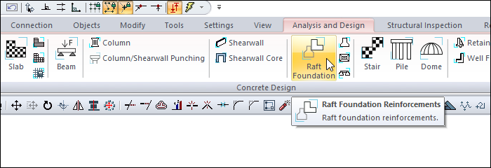
After analysis, you can access it by clicking on the Raft Foundation command under the Concrete Design title of the ribbon menu Analysis and Design tab .
General Specifications of Slab (Raft Foundation) Reinforcements Dialogue
|
Summary Information The summary information about the line where the cursor is located is given in the name of the dialog in the format of Floor, Name, Calculation Axis No, Operation Type, Reinforcement type. 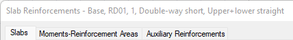
For example Basement, RD, 1, Double Front short, top + bottom straight |
|
Using the Shift key In this tab, you can select more than one row with the Shift key, enter a value by double-clicking any cell whose value is open to change, and you can make that value apply to all selected rows. |
|
Using the Ctrl key Ctrl key, on the other hand, selects the lines in between one by one. |
|
Show horizontal It displays the horizontal reinforcements in the slabs by filtering, and the vertical reinforcement is hidden. |
|
Show verticals It displays the vertical reinforcements in the slabs by filtering, and the horizontal reinforcements are hidden. |
|
All Floors It lists the beams on the screen across the entire floor. |
|
Select Selects the element on the data screen. |
|
Previous The cursor moves to the previous line. |
|
Next The cursor goes to the next line. |
|
Filter It is used to define certain conditions and filter only the elements that satisfy that condition. |
|
OK It saves the changes made and closes the dialog. |
|
Cancel Closes the dialog without saving the changes made. |
Insufficiency Code Description and Recommended Solution
|
Insufficiency Code |
Description |
|---|---|
|
Çd |
The raft foundation is designed as a double-reinforced section.
|
|
Min |
The minimum thickness requirement as per the Design Code is not satisfied. Solutions: Increase slab thickness; ensure that the raft slab thickness is not less than 30 cm. |
|
S |
The Deflection Limits as per the Design Code are not satisfied. Solutions: Increase slab thickness; adjust reinforcement layout to reduce deflection. |
|
As(-) |
The provided reinforcement area is insufficient.
|
|
Zg |
Soil bearing capacity is exceeded.
|
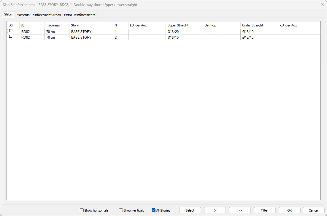
Slabs Tab
|
Specifications |
|---|
|
DS It is the rebar fixing column. If marked, the rebars are fixed. When changes are made to the slab rebars, the DS is automatically marked and the rebars remain fixed even if the slab is made of concrete. If the DS is not marked, the rebars are determined again after the analysis according to the rebar selection conditions. |
|
ID 
It is the name of the story that appears in the plan. (RD1, RD2, RD10 etc.) In case of negativity, the term related to negativity is added next to the name of the plate. R101 (Min) etc will appear. |
|
Thickness 
The thickness of the raft foundation appears in this cell. |
|
Story 
The name of the story where the raft foundation is located appears in this cell. |
|
N It is the number of concrete calculation axis. (1,2,3,4 etc.) Since there can be more than one concrete calculation axis on the same plate, the numbers of the calculation axes are followed from the N column. |
|
LUnder aux 
The diameter and the spacing in cm of the additional rebar calculated under the left support section on the relevant concrete calculation axis are shown. If double clicked on the cell, the diameter and spacing of the rebar can be changed. |
|
Upper straight 
It is the diameter and the spacing in cm of the rebar located above the slab section in the relevant concrete calculation axis. The diameter and range of the rebar can be changed by double clicking on it. 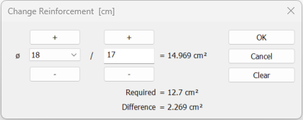
If the reinforcement type is selected as upper + under straight reinforcement, the required and available reinforcement area calculations are made and the difference is shown. |
|
Bent-up 
It is the diameter and interval in cm of the pleat rebar with slab on the relevant concrete calculation axis. The diameter and range of the rebar can be changed by double clicking on it. |
|
Under straight 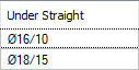
It is the diameter and interval in cm of the rebar located under the slab section on the relevant concrete calculation axis. The diameter and range of the rebar can be changed by double clicking on it. 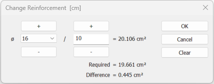
If the reinforcement type is selected as upper + under straight reinforcement, the required and available reinforcement area calculations are made and the difference is shown. |
|
RUnder aux 
It is the diameter and the interval in cm of the additional rebar calculated under the right support section in the relevant concrete calculation axis. The diameter and spacing of the rebar can be changed by double clicking on the cell. |
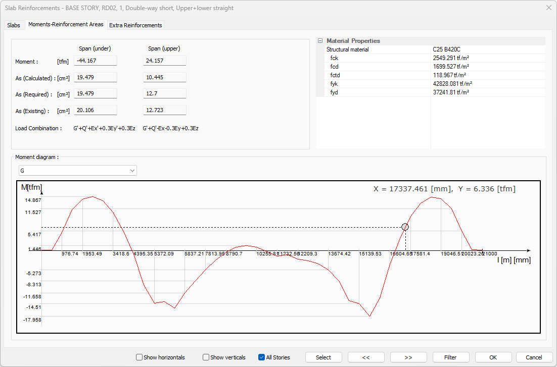
Moments - Reinforcement Areas Tab
|
Specifications |
|---|
|
Span (under) 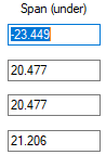
It defines the lower part of the section in the slab opening in the analyzed concrete calculation axis. |
|
Span (upper) 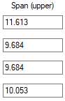
It defines the upper part of the section in the slab opening in the analyzed concrete calculation axis. |
|
Moment The design moment value that is taken as basis in concrete design is given. |
|
As (Calculated) It is the area of rebar found for a width of 100 centimeters from the design moment. |
|
As (Required) It is the rebar area calculated from the design moment and the one that is greater than the rebar area to be placed as per the regulation. |
|
As (Existing) It is the total rebar area value available in the section after the rebar selection. |
|
Load combination You can examine the moment diagram by choosing the combination you want from the combination list. |
|
Structural material Shows the structural material of the slab. |
|
fck The characteristic of concrete is its compressive strength. |
|
fcd The characteristic calculation of concrete is its compressive strength. |
|
fctd The characteristic calculation of concrete is its tensile strength. |
|
fyk Reinforcement is the yield strength of rebar. |
|
fyd It is the calculation strength of rebar steel. |
|
Moment diagram The moment diagram according to the selected combination is displayed on the analyzed calculation axis. When you move the mouse over the moment diagram, the position of the cursor on the diagram is shown. X represents the Y moment value for the left distance. 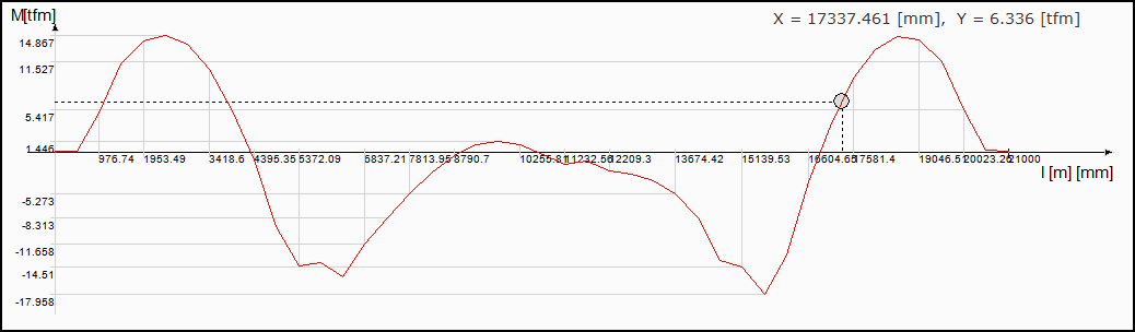
|
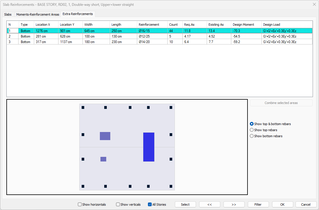
Extra Reinforcements Tab
When flat rebar design is made on top and bottom for beams and non-beam slabs, the additional diameter and number are specified to cover the entire slab system. If the rebar calculation axis is selected as top and bottom straight, the program automatically creates additional zones on the supports required as a result of the plate analysis. After analysis and concrete design, the diameter and number of additional rebars are determined and listed on this tab.
In the tab, detailed information about the additional rebar is given in the table, and in the schematic plan view, the information about the area of the additional rebar is given. Blue areas represent upper additional rebar zones, red areas represent lower additional rebar zones.
|
Specifications |
|---|
|
N It is the number of the addition. It is assigned automatically by the program. |
|
Type 
Indicates the location of the additional rebar. If it is lower, additional rebar is at the bottom, if it is over, additional rebar is at the top. |
|
Location X 
It is the distance of the region where the additional rebar is located to the global y-axis. |
|
Location Y 
It is the distance of the region where the additional rebar is located to the global x-axis. |
|
Width 
It is the width of the region with additional rebar. |
|
Length 
It is the length of the region where additional rebar is located. |
|
Reinforcement 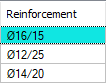
It is the diameter and range of the additional rebar to be placed in the region where the additional rebar is located. |
|
Count It is the number of additional rebar to be placed in the area where the additional rebar is located. |
|
Req. As 
It is the amount of rebar that should be placed in the area where additional rebar is located, as per the calculation or regulation. |
|
Existing As 
It is the amount of rebar placed in the area of additional rebar. |
|
Design moment 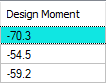
It is the design moment that gives the greatest rebar in the area where the additional rebar is located. |
|
Design load 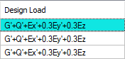
The most unfavorable loading type, in which the design moment is calculated, is written. |
|
Combine selected areas Selected additional rebar areas from the list are combined. |
|
Show top & bottom rebars If the option is selected, top and bottom additional rebars are shown. |
|
Show top rebars If the option is selected, top additional rebars are shown. |
|
Show bottom rebars If the option is selected, bottom additional rebars are shown. |
Next Topic
Related Topics