
How does ideCAD design Column-Foundation Connection (Stiffened Baseplate) according to AISC 360-16 & Design Guide 1?
-
Limit states of Column-Foundation Connection (Stiffened Baseplate) are checked automatically according to AISC 360-16 & Design Guide 1.
-
Anchor Rod Concrete Pullout limit state is checked automatically according to ACI 319M-18.
Symbols
Ab: Non-threaded bolt web characteristic cross-sectional area
Ag: Gross area
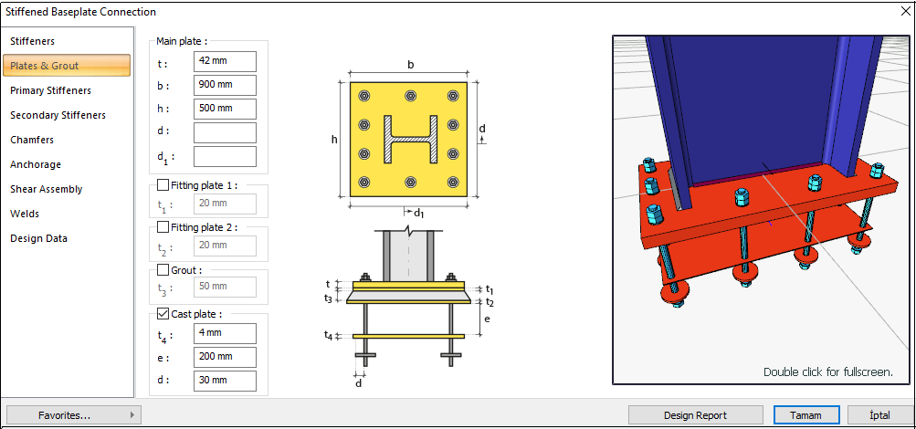
A1: Area of the base plate,
A2: Area of the supporting surface
d: Characteristic diameter of the stem of the bolt (the diameter of the non-threaded stem of the bolt)
dh: Bolt hole diameter
e: equivalent eccentricity
fc: Concrete design compressive strength
Fy: Structural steel characteristic yield strength
Fu: Structural steel characteristic tensile strength
s: Distance between bolt-hole centers
Lc: The clear distance between bolt holes
Le: The distance from the center of the bolt hole to the edge of the assembled element
Leh: The horizontal distance from the center of the bolt hole to the edge of the assembled element
Lev: The vertical distance from the center of the bolt hole to the edge of the assembled element
t: Plate thickness
w = Size of weld leg, in. (mm)
Rn: Characteristic strength
GEOMETRY CHECKS
Bolt Spacing
The distance between the centers of bolts is checked per AISC 360-16.
|
smin ≥ 3d |
AISC 360-16 J3.3 |
|
|
|
s |
180 mm |
|
|
|
d |
24 mm |
s =180 mm > smin = 3*24=72 mm |
√ |
Horizontal Edge Distance
The distance from the center of the hole to the edge of the connected part in the horizontal direction is checked per AISC 360-16.
|
Leh ≥ Le-min |
AISC 360-16 J3.4 |
|
|
|
Leh |
70 mm |
L eh ≥ 2d = 2 * 24 = 48 mm conformity check for application |
√ |
|
Le- min |
30 mm |
Minimum distance check according to Table J3.4 |
√ |
Vertical Edge Distance
The distance from the center of the hole to the edge of the connected part in the vertical direction is checked per AISC 360-16.
|
Lev ≥ L e-min |
AISC 360-16 J3.4 |
|
|
|
Lev |
45 mm |
|
|
|
Le-min |
30 mm |
Minimum distance check according to Table J3.4 |
√ |
Strength Controls
Base Plate Thickness (Compression)
The required plate thickness is determined according to AISC Steel Design Guide 1 Eq.3.3.15a.
|
fc |
25000 kN/m2 |
|
|
A1 |
|
|
|
A2 |
|
|
|
qmax |
|
|
|
fp(max) |
|
|
|
fp(max) |
|
|
|
e |
|
|
|
ecrit |
|
|
|
Y |
|
|
|
Y |
|
|
|
f |
|
|
|
le |
45 mm |
|
|
l |
max(m,n)=141.25 |
|
|
m |
|
|
|
n |
|
|
|
h |
650 mm |
|
|
b |
300 mm |
|
|
N |
900 mm |
|
|
B |
500 mm |
|
|
M |
365.17 kNm |
|
|
P |
739.22 kN |
|
|
y |
355 N/mm2 |
|
|
treq |
|
AISC DG-1-2nd 3.3.15.a |
|
Required |
Available |
Ratio |
Control |
|---|---|---|---|
|
41.11 mm |
42 mm |
0.979 |
√ |
Base Plate Thickness (Tension)
The required base plate thickness for tension is determined according to AISC Steel Design Guide 1 Eq.3.4.7a.
|
fc |
25000 kN/m2 |
|
|
A1 |
|
|
|
A2 |
|
|
|
qmax |
|
|
|
e |
|
|
|
ecrit |
|
|
|
T |
|
|
|
Y |
|
|
|
Y |
|
|
|
f |
|
|
|
x |
|
|
|
le |
45 mm |
|
|
m |
|
|
|
h |
650 mm |
|
|
N |
900 mm |
|
|
B |
500 mm |
|
|
M |
365.17 kNm |
|
|
P |
739.22 kN |
|
|
Fy |
355 N/mm2 |
|
|
treq |
|
AISC DG-1-2nd 3.4.7a |
|
Required |
Available |
Ratio |
Control |
|---|---|---|---|
|
15.312 mm |
42 mm |
0.365 |
√ |
Anchor Rod Tensile Rupture
The limit state of the anchor rod tension rupture is checked according to AISC 360-16.
|
Ab |
|
|
|
Fn |
750000 kN/m2 |
|
|
Rn |
|
AISC 360-16 J3-1 |
|
ΦRn |
|
|
|
Required |
Available |
Ratio |
Control |
|---|---|---|---|
|
28.779 kN |
254.469 kN |
0.113 |
√ |
Anchor Rod Concrete Pullout
The limit state of the anchor concrete pullout is checked according to ACI 318M-08.
|
Ψ |
1.0 |
ACI 318M-08 D.5.3.6 |
|
Np |
|
ACI 318M-08 (D-15) |
|
Abgr |
7401.592 mm2 |
|
|
fc |
25000 kN/m2 |
|
|
Rn |
|
ACI 318M-08 (D-14) |
|
ΦRn |
|
|
|
Required |
Available |
Ratio |
Control |
|---|---|---|---|
|
28.779 kN |
1036.222 kN |
0.028 |
√ |
Anchor Rod Shear
The calculation is made using the Elastic method, one of the methods selected in the steel analysis settings tab. In this check, the operation is performed on half of the symmetry axis and is calculated to form a force pair with the required force.
|
Ab |
|
|
|
Fn |
|
|
|
Rn |
|
AISC 360-16 J3-1 |
|
ΦRn |
|
|
|
Required |
Available |
Ratio |
Control |
|---|---|---|---|
|
9.885 kN |
152.681 kN |
0.065 |
√ |
Bolt Bearing on Plate
The bearing strength limit states of the base plate, which are “shear tear out” and “ovalization of bolt hole” for both end and inner bolts, are checked according to AISC 360-16.
|
dh |
24+3=27 mm |
|
|
Lc,edge |
|
|
|
Rn |
|
AISC 360-16 J3-6a |
|
Rn-edge |
|
|
|
Rn |
|
|
|
ΦRn |
|
|
|
Required |
Available |
Ratio |
Control |
|---|---|---|---|
|
9.885 kN |
559.629 kN |
0.018 |
√ |