
ICONS
A s = Longitudinal reinforcement area
a i = Distance between the axes of the vertical reinforcement around the section
b o = Cross section size between the axes of the stirrupssurrounding thecore concrete
E c = Elasticity module of concrete
E s = Elasticity modulus of reinforcement steel
f c = Concrete compressive stress in confined concrete
f cc = Confined concretestrength
f co = Compressive strength of unconfined concrete
f e = Effective wrapping pressure
f s = Stress in reinforcing steel
f sy = Yield strength of reinforcement steel
f su = Tensile strength of reinforcing steel
f yw = Yield strength of transverse reinforcement
h o = Size of cross section between the axes of stirrupssurroundingcore concrete
k e = Coiling Efficiency Coefficient
s = Transverse reinforcement range
ρ s =Volumetric proportion of the total transverse reinforcement (rectangular in cross-section ρ s = ρ x + ρ y )
ρ x , ρ y = transverse reinforcement volume fraction in the appropriate direction
ε c = concrete compressive unit deformation of
ε c = maximum pressure unit strain of the confined concrete
ε s = the reinforcing steel the strain
ε sy = flow volume of deformation of the reinforcing steel
ε sh =Unit deformation of reinforcement steel at the beginning of hardening
ε water = rupture strain of reinforcing steel
5A.1. WRAPPED AND NON-WRAPPED CONCRETE MODELS
The following stress-strain relations are defined for confined and unconfined concrete to be used in the evaluation according to deformation with Nonlinear Methods , when no other model is selected (Figure 5A.1) .
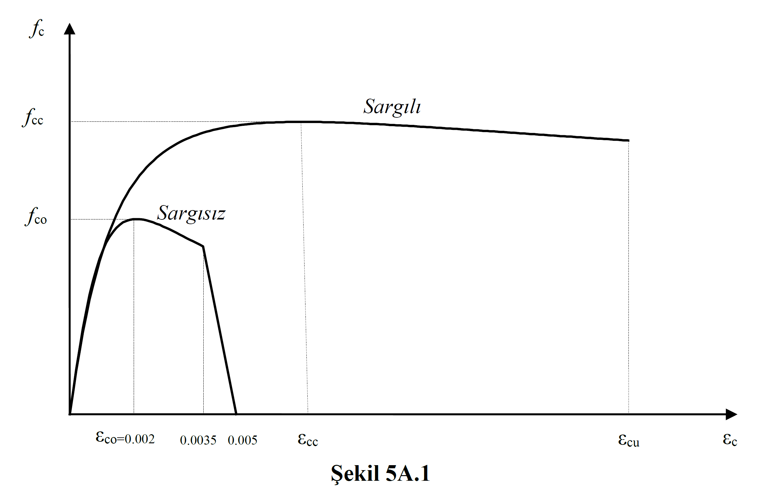
(a) In confined concrete, the concrete compressive stress f c is given by the equation in Equation (5A.1) as a function of the pressure strain ε c :

Confined concrete strength in this equation f cc raw edge strength concrete with f co relationship between Eq. (5A.2) are given.

Here, the effective winding pressure f e can be taken as the average of the values given in Equation (5A.3) for two perpendicular directions in rectangular sections :

In these relations, f yw is the yield strength of the transverse reinforcement, ρ x and ρ y are the volumetric ratios of the transverse reinforcement in the respective directions, and k e is the coefficient of winding efficiency defined in Equation (5A.4) .

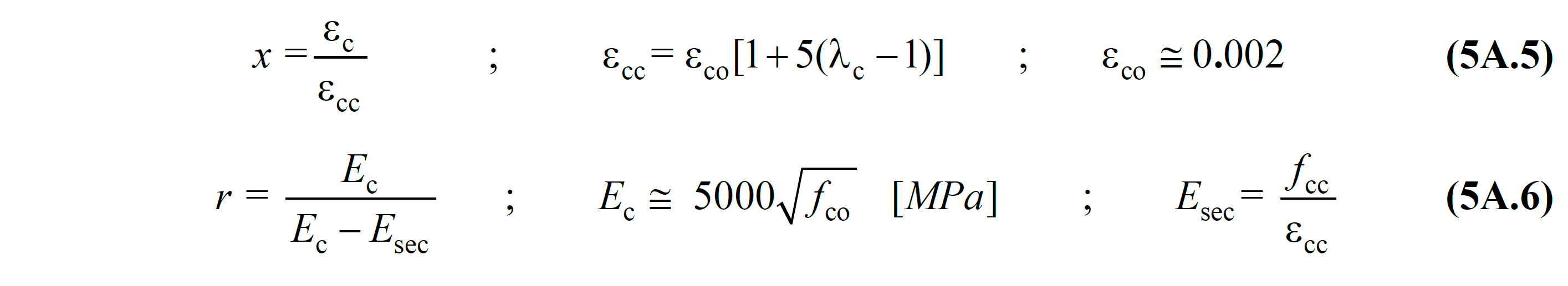
Here, a i shows the distance between the axes of the longitudinal reinforcements around the section, b o and h o the section dimensions between the axes of the stirrups surrounding the core concrete, s is the spacing between the axes of the stirrups in the longitudinal direction, and A s indicates the longitudinal reinforcement area. Eq. (5A.1) wherein the normalized correlation with concrete units related to strain the x variable r Eq. (5A.5) and Eq. (5A.6) are given in.
5A.2. REINFORCEMENT STEEL MODEL
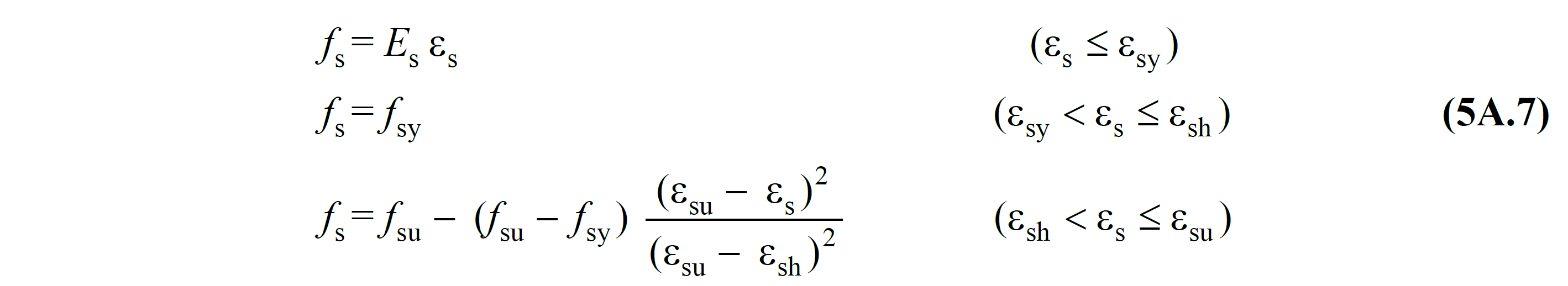
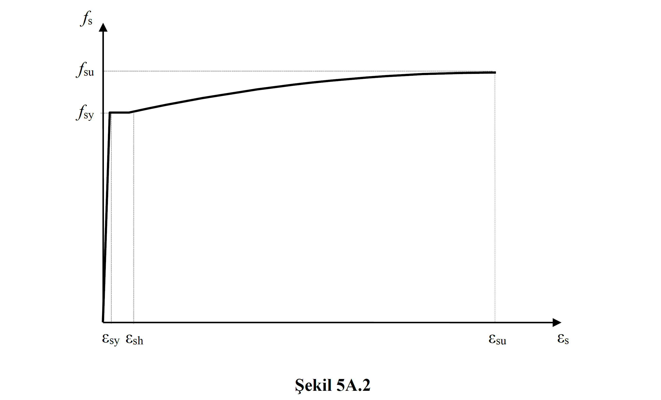
Nonlinear methods for use in the evaluation according to the deformation, for the reinforcement steel in Eq. (5A.7) wherein the stress-strain relationship are defined (Figure 5A.2) :
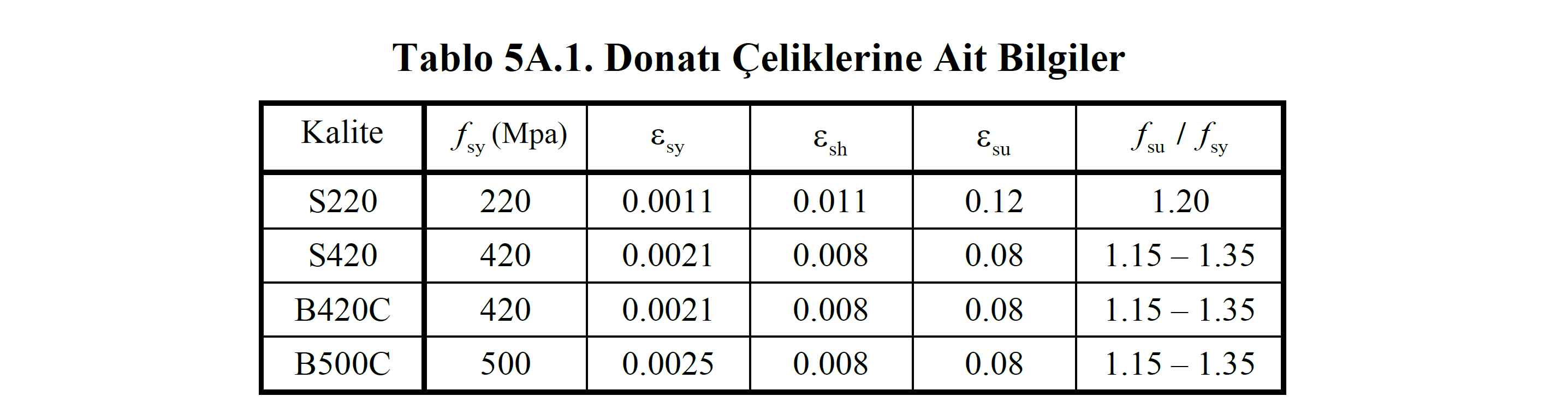
The elastic modulus of reinforcement steel is E s = 2x10 -5 MPa. Other information on reinforcement steels are given in Table 5A.1 .
Related Topics