-
The mass model used for dynamic analysis is created automatically.
-
Mode shapes and modal vibration periods are calculated automatically.
ICONS
m i = Total mass of the i th floor
m iθ = Mass moment of inertia of the i th floor
m j (S) = Single mass acting on typical finite element node j
UX = Translation in the direction of the joint point ( X ) in the three-dimensional analysis model
UY = Translation of the joint in the (Y) direction in the
three-dimensional analysis model UZ = The translation of the joint in the (Z) direction in the
three-dimensional analysis model, RX = Rotation of the nodal point (X) around the axis in the three-dimensional analysis model,
RY =Rotation of the node (Y) axis in the three-dimensional analysis model
RZ = Rotation of the node (Z) axis in the three-dimensional analysis model
Dynamic Behavior of Multi-Degree of Freedom Systems
The degrees of freedom of a structure system is the number of independent variables required to determine the position of the system in motion. If more than one of these independent variables needs to be known, these systems are multi-degree-of-freedom systems. In three-dimensional dynamic analysis application, multi-degree-of-freedom systems are used and 6 independent variables are taken into account: displacements in the x, y and z axes and rotations around these axes. In reality, all systems are made up of continuous masses. However, when performing dynamic analysis with finite elements, it is assumed that the masses are gathered at the element nodes.
Also see. : Full and Semi-Rigid Diaphragm
The dynamic behavior of multi-degree-of-freedom systems is expressed by the following set of differential equations. This equation is also called the equation of motion.
Here
,
,
respectively, acceleration, velocity and displacement vectors, {p(t)} load vector, [m] , [c] , [k] mass, damping and stiffness matrices.
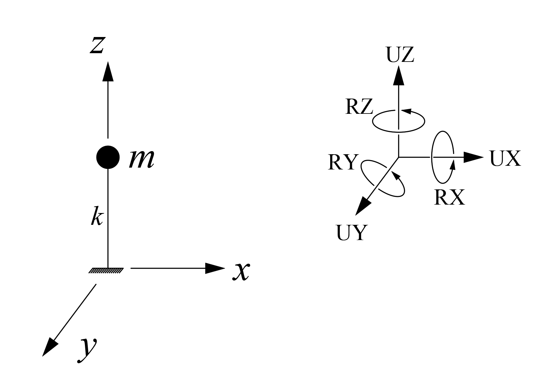
The mass matrix [m] differs in systems with rigid diaphragms and semi-rigid diaphragms. In systems solved with a fully rigid diaphragm, the masses are gathered at the floor center of gravity and dynamic analysis is performed. In the picture below, there is the 1st mode shape of a structure solved with a fully rigid diaphragm. In the system, where dynamic analysis is performed with a fully rigid diaphragm, the masses are gathered at the floor center of gravity as seen in the figure.
In systems solved with a fully rigid diaphragm, the masses are gathered at the floor center of gravity and dynamic analysis is performed. The mi value specified in TBDY 4B.1.3(a) refers to the masses collected from the floor center of gravity. The displacements defined in the x and y horizontal directions at the center of mass of any ith floor slab and the rotation around the vertical axis passing through the floor mass center are taken into account and the floor mass mi and the floor mass moment of inertia miθ corresponding to these degrees of freedom are defined. In the above figure, in the system where dynamic analysis is performed with a fully rigid diaphragm, the masses collected at the floor center of gravity are calculated in m , as described in TBDY 4B.1 .stands for the i term.
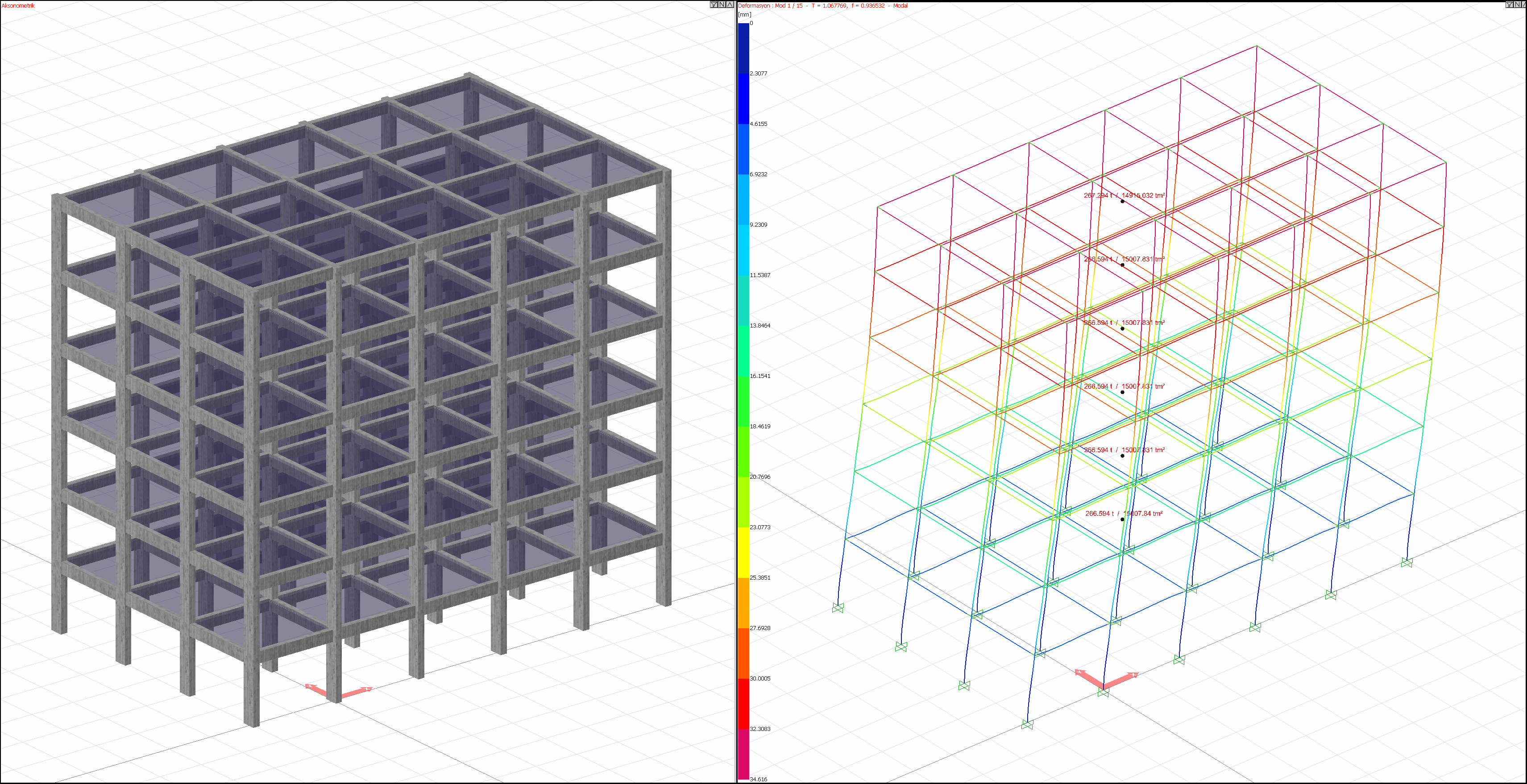
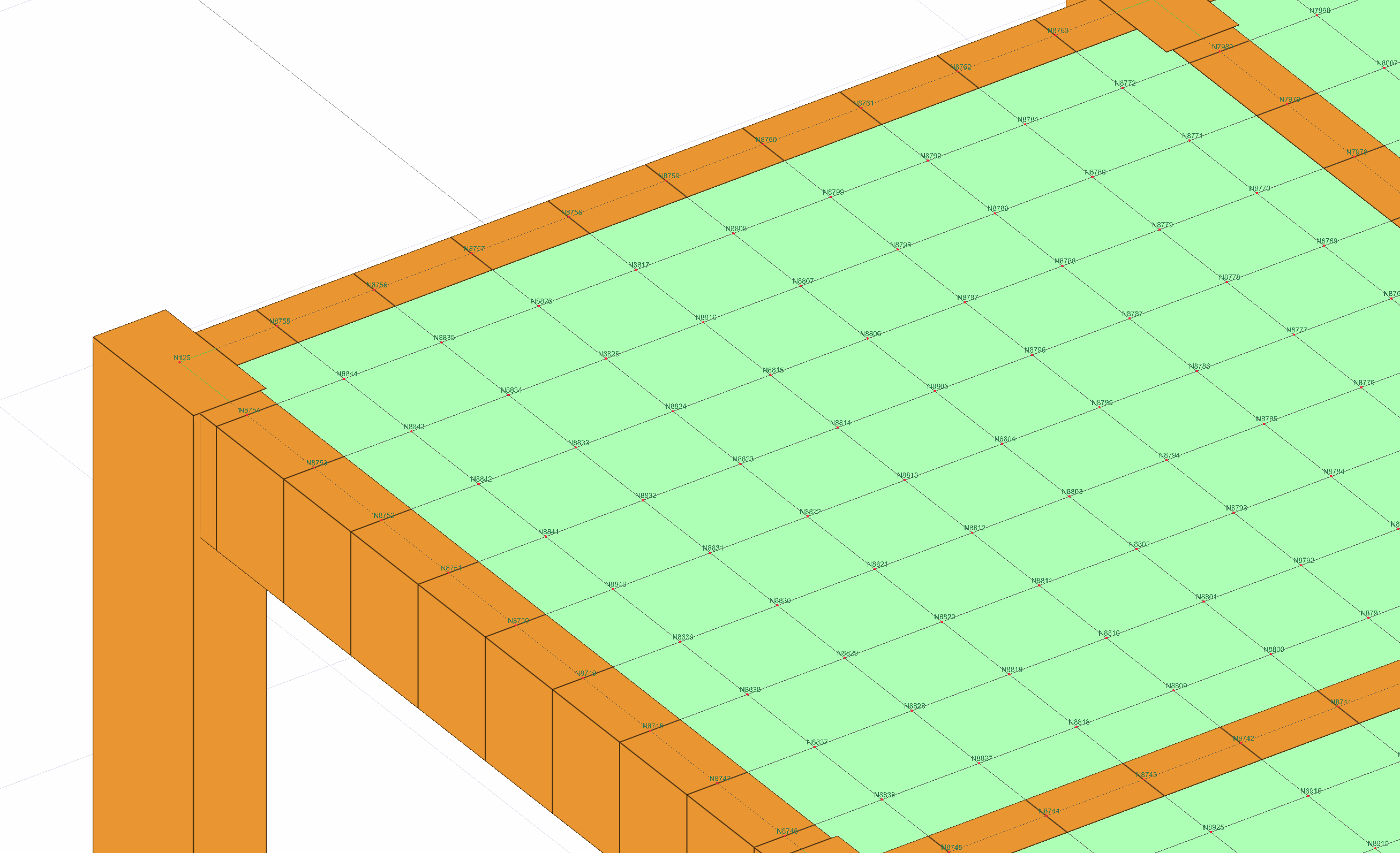
In systems solved with a semi-rigid diaphragm, the masses are defined at the nodes of the finite elements and dynamic analysis is performed. In the picture below is the 1st mode shape of a structure solved with a semi-rigid diaphragm.
In systems where dynamic analysis is made with a semi-rigid diaphragm, the masses are defined at the nodes of the finite elements. The mi value specified in TBDY 4B.1.3(b) corresponds to the mass value collected at the floor gravity center when floor slabs are taken as rigid diaphragms . The mj (S) value specified in TBDY 4B.1.3(b) is the two-dimensional finite elements containing the degrees of freedom related to the displacements within their planes of the floor slabs and the masses defined at the nodal points of the modeled elements. mj ( S)The index j in the term is used for each node and corresponds to the nodal points in the analysis model shown below.
Mode Shapes and Modal Vibration Periods
The mode shapes and vibration periods of a structural system are obtained from the solution of the equation of motion in the case of undamped free vibration without external load. In this case, the situation without damping and external load in the equation of motion is expressed as follows.
Free vibrational motion is a simple harmonic motion and is expressed by the sine function. In this case, the displacements {x} are obtained by the following equation.
In this equation {A} is the amplitude vector of the motion and ω is the angular frequency. With the second derivative of {x} with respect to timeequation is obtained and this matrix shows the acceleration values.
If the second derivative of the {x} equation with respect to time is substituted in the equation of motion without damping and external load, an eigenvalue problem as follows is obtained.
The solution of the obtained homogeneous linear equation system is possible only if the determinant of the coefficients matrix is zero.
When the above determinant is expanded i. a polynomial of degree is obtained. The roots of this polynomial give the eigenvalues ω 2 . By substituting each eigenvalue found in the equation, the eigenvectors {Φ} for each mode are found. For any n'th mode the following equation must be satisfied.
As a result, in a multi-degree-of-freedom system, the solution result is as many degrees of freedom as angular frequency ω n and the corresponding mode shape { Φ n }. The mode shape shows the position taken by the system when it vibrates with the relevant frequency. The relationship between the vibration period Tn and the angular frequency for the nth mode is as follows. The period values obtained as a result of the dynamic analysis are obtained in this way.
In any vibration mode, displacements can take any value, provided the ratio between them remains constant. Mode vectors show orthogonality with respect to both the mass matrix and the stiffness matrix . By using this feature, the largest amplitude unit value in any mode is taken and other amplitudes in the same mode are proportioned to the largest amplitude, and the corresponding mode is normalized.
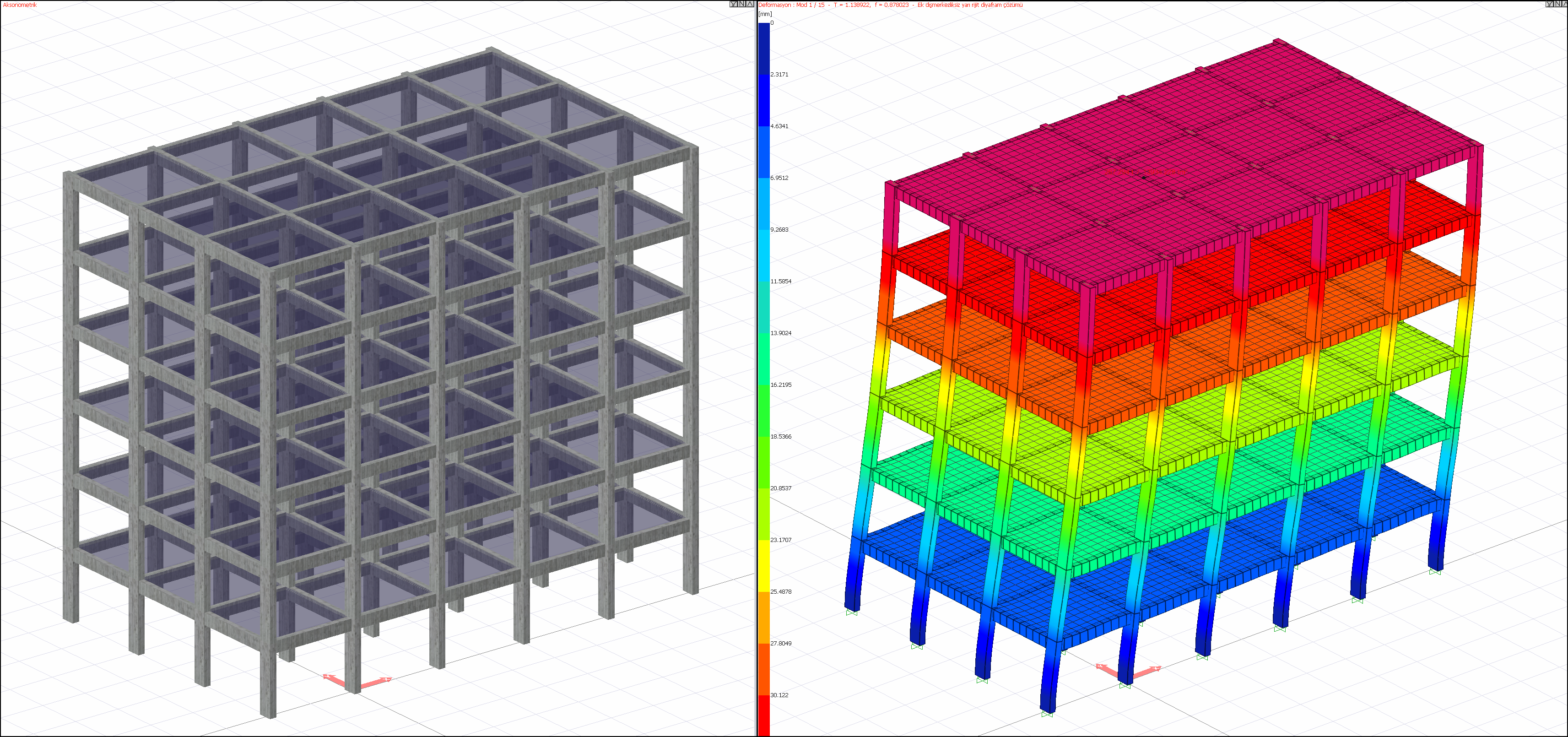
These normalized mode shape vectors are used in the Modal Calculation Parameters calculations described in TBDY 4B.1 . In the picture below, the deformation results of the mode shapes found as a result of the dynamic analysis of a sample structure are shown. These values are also normalized mode vectors values. Since the semi-rigid diaphragm solution is made, the strain at each node corresponds to an element of the mode vector.
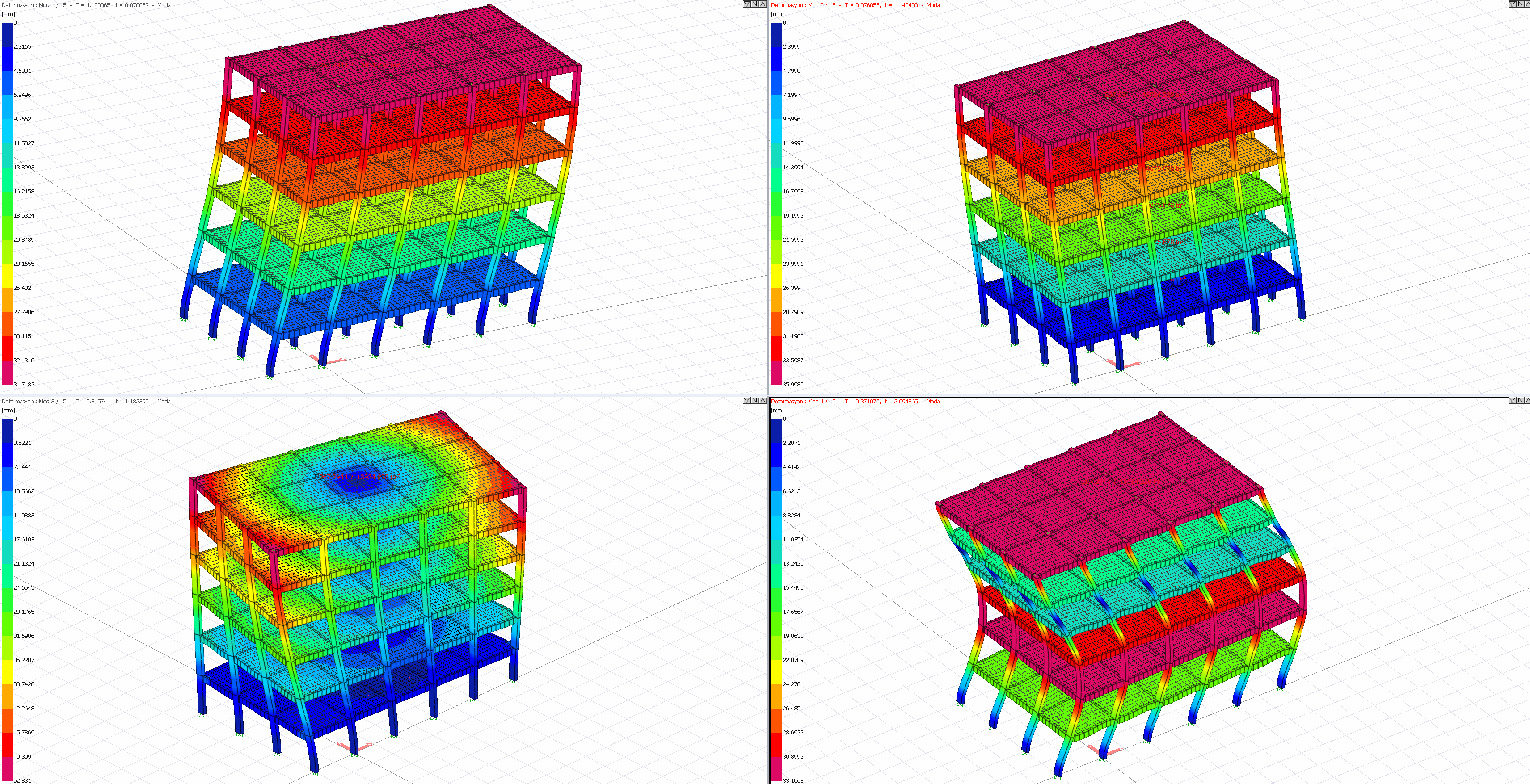
The deformations in the mode shapes can take any value provided the ratio between them remains constant. For this reason, the deformations calculated in the mode shapes cannot be used in the design, they can only show the shape that the structure will take in case of vibration in the relevant mode. These mode shapes, which are calculated to take into account the earthquake effect correctly, are used in the Mode Combination Method together with the Horizontal Elastic Design Spectrum .
As a result of the modal analysis performed in ideCAD Static, the masses used for the modal analysis, the natural vibration periods calculated for each mode, and the angular frequency values can be examined in the Modal Analysis Report .