
|
Single element, assembly, application and plan, column anchorage etc. of the project whose Analysis+Design is done. Create steel drawings. |
-
Architectural objects should be deleted when creating steel drawings.
-
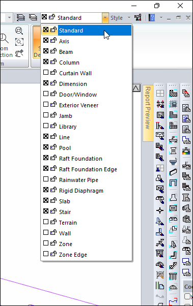
Turn off the Wall layer from the layer list.
-
Close the layer list by pressing the Esc key on the keyboard.
-
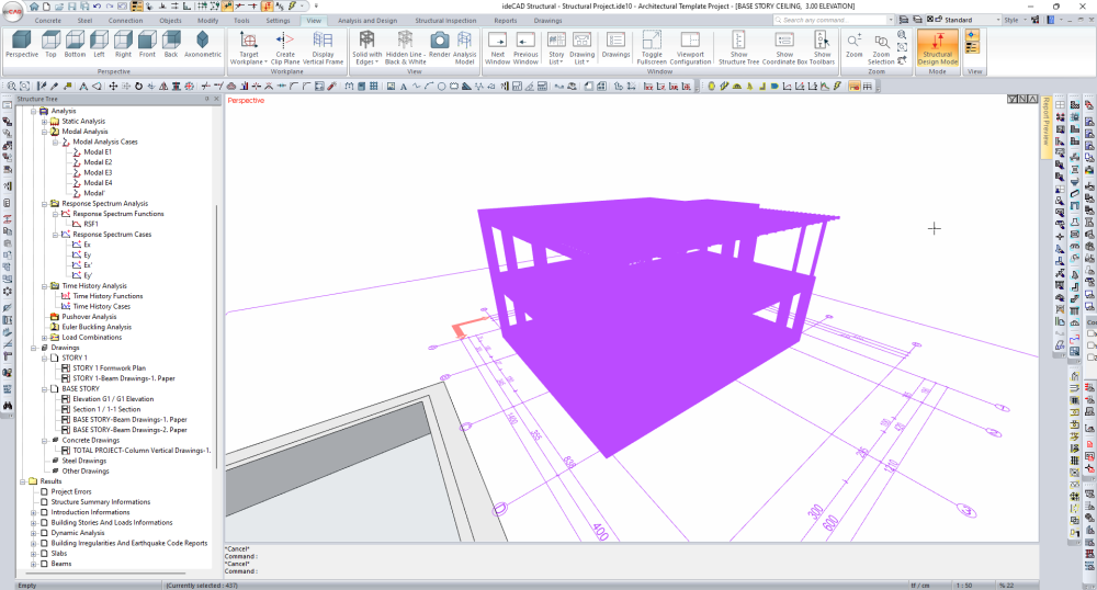
Select all elements from the perspective view with the Select All command.
-
Remove the pool from the selection by clicking on the pool with the left mouse button.
-
Open all closed layers from the layer list .
-
Close the layer list by pressing the Esc key on the keyboard .
-
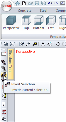
Click on the Invert Selection command.
-
Architectural objects will be selected.
-
Delete architectural objects by pressing the Delete key on the keyboard .
-
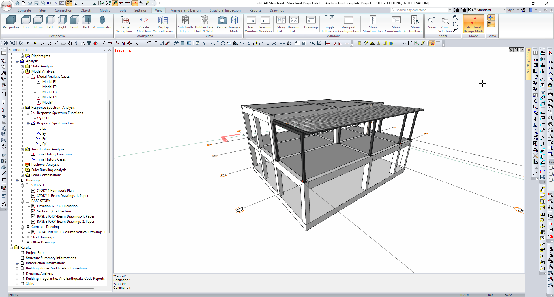
Open the STORTY 1 CEILING page.
-
Select all elements from the perspective view with the Select All command.
-
Open all closed layers from the layer list.
-
Close the layer list by pressing the Esc key on the keyboard.
-
Click on the Invert Selection command.
-
Delete architectural objects by pressing the Delete key on the keyboard .
-
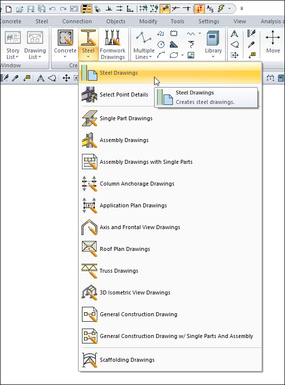
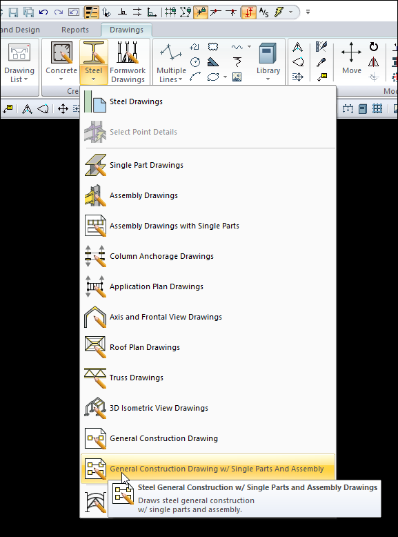
Click the Drawings tab in the Ribbon menu.
-
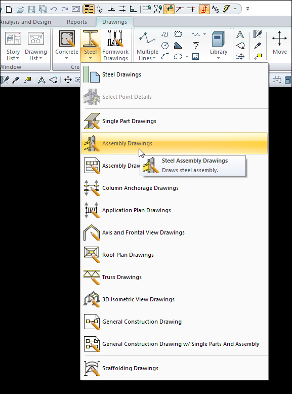
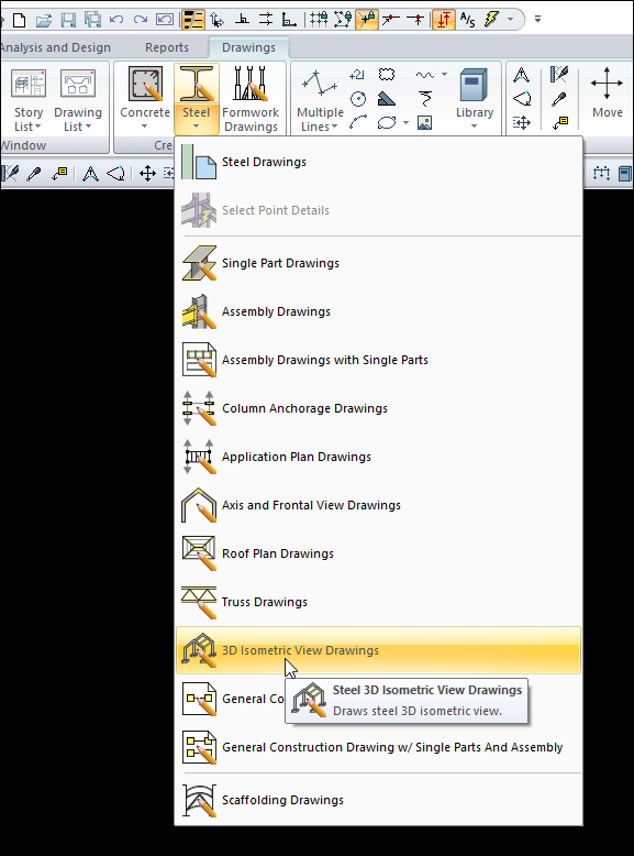
Open the Steel drawing list from the Create Drawing heading.
-
Click the Steel Drawings command.
-
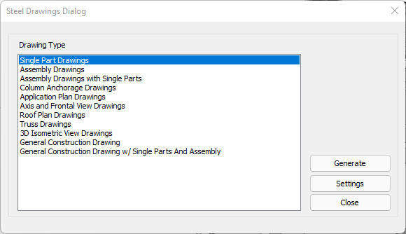
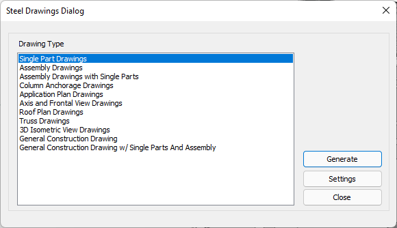
The Steel Drawings Dialog will open.
-
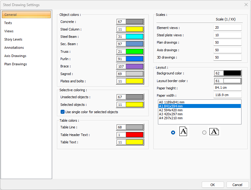
Click the Settings button.
-
Check the steel drawing settings from the Steel Drawing Settings dialog that opens .
-
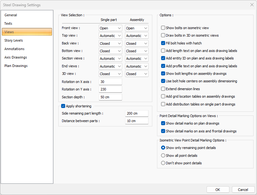
Click the View tab.
-
Enter 30 as the rotation on X axis line and 230 as the rotation on Y axis line.
-
Click the OK button to close the dialog.
-
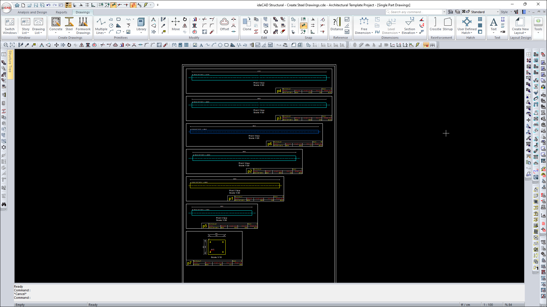
Select Single Part Drawings from the Steel Drawings Dialog and click the Generate button.
-
Single Part Drawings will be created.
-
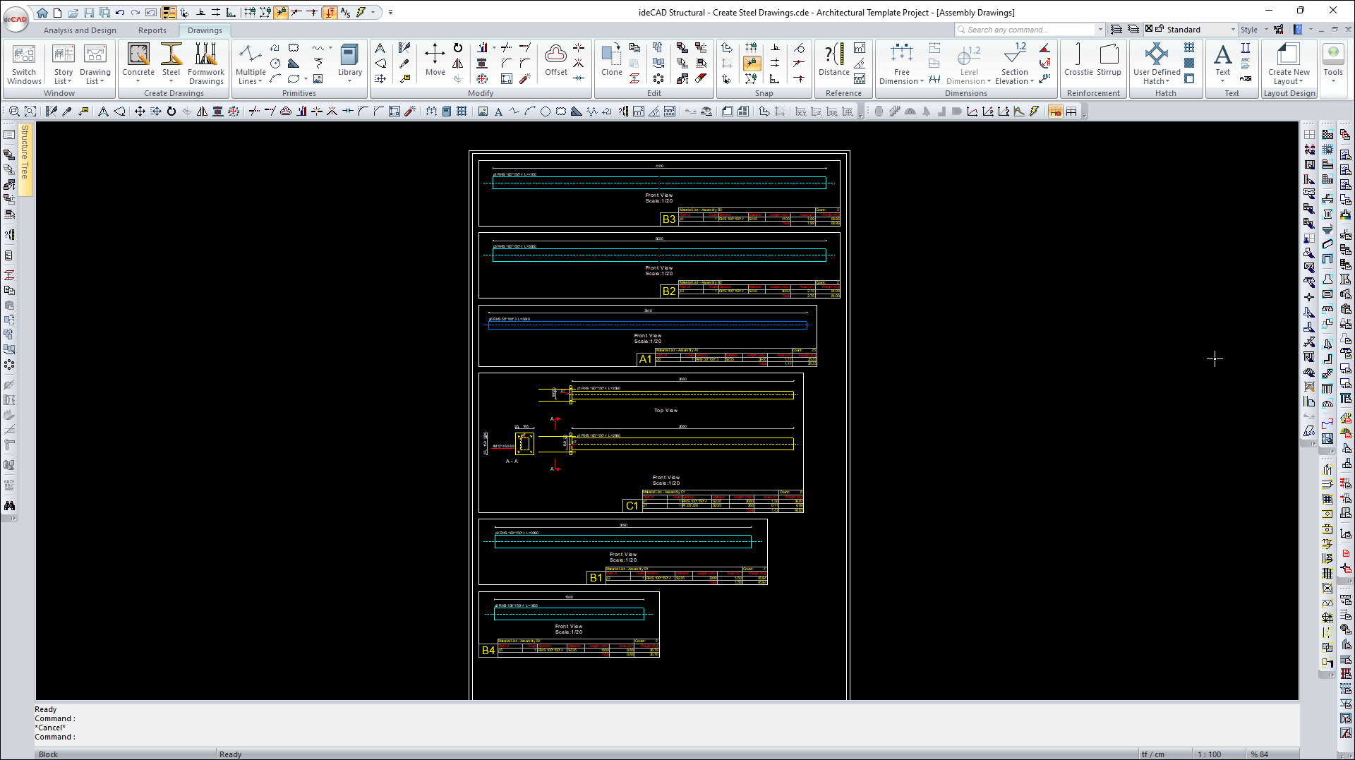
Click on Steel Assembly Drawings from the list of Steel drawings .
-
Assembly Drawings will be created.
-
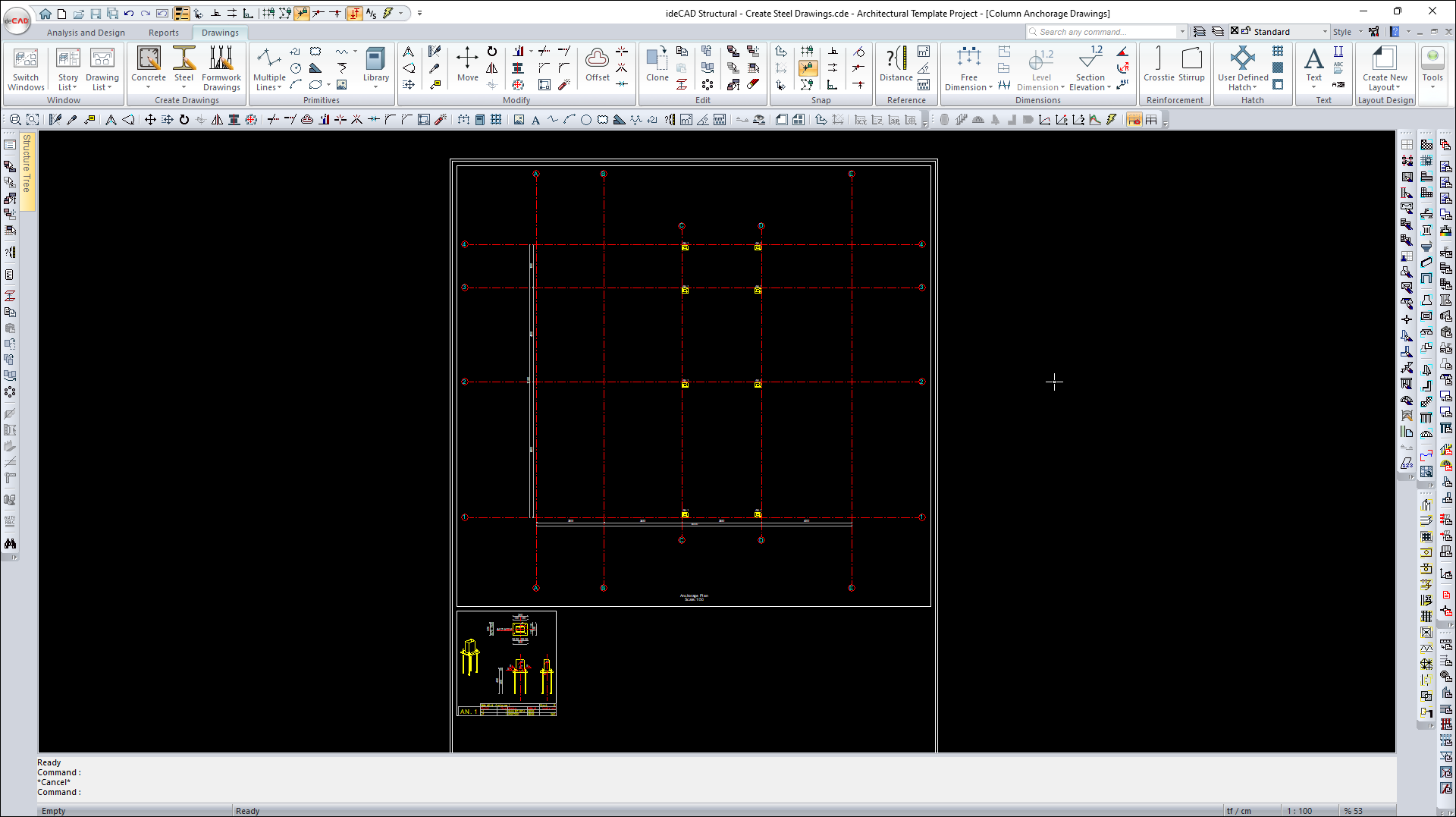
Click on the Column Anchorage Drawings command from the Steel drawing list.
-
Column Anchor Drawings will be created.
-
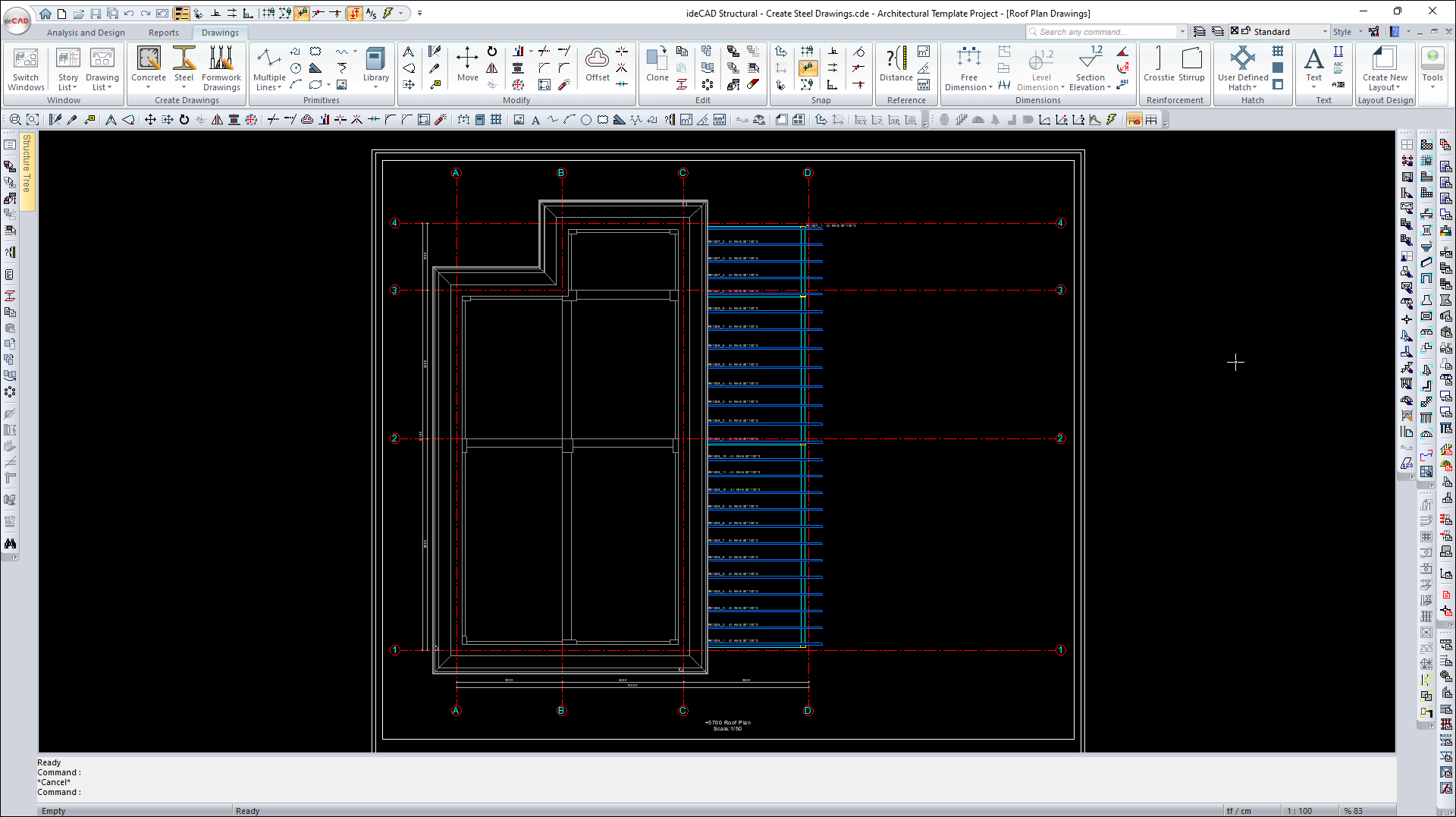
Click on the Roof Plan Drawings command from the Steel drawing list .
-
Roof Plan Drawings will be created.
-
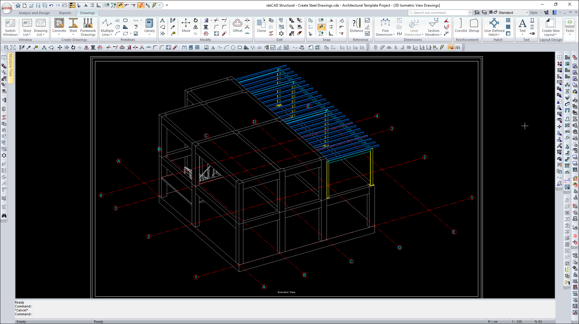
Click on the 3D Isometric View Drawings command from the steel drawing list.
-
3D Isometric View Drawings will be created.
-
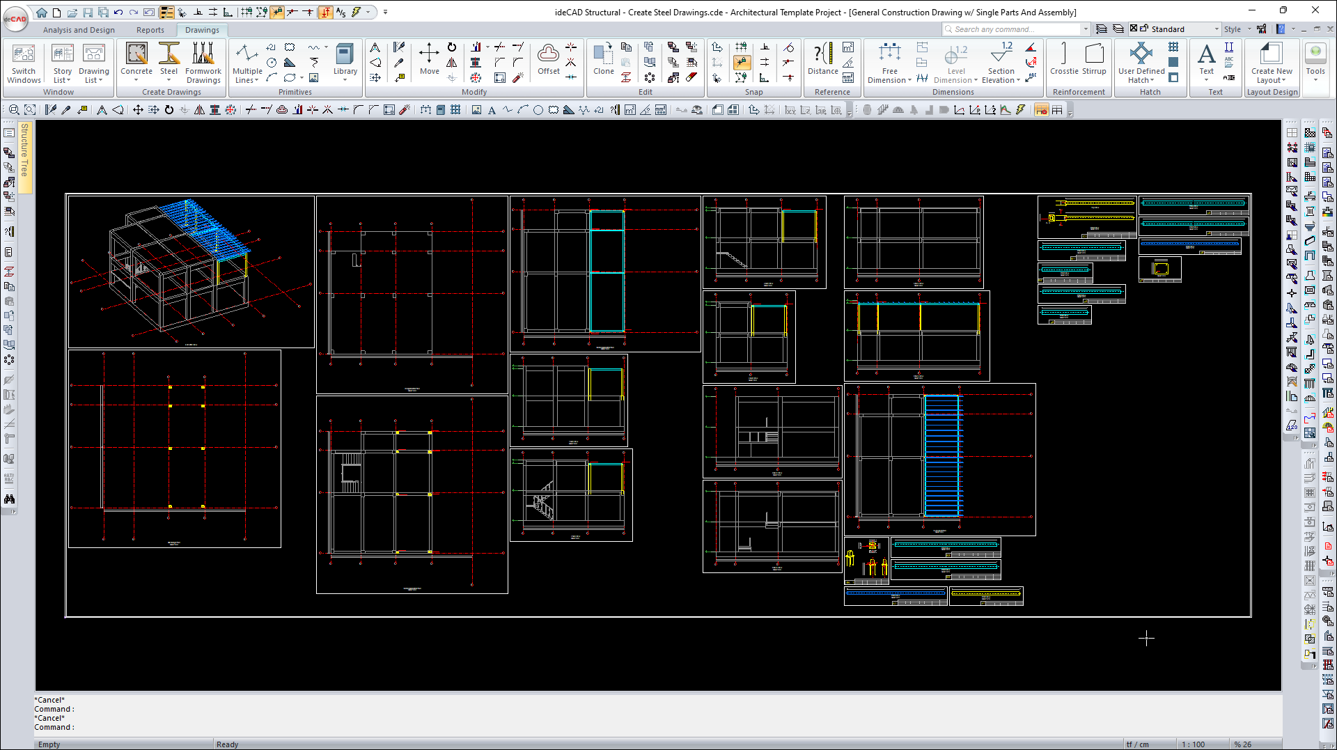
Click on the General Construction Drawings w/ Single Parts and Assembly command from the Steel drawing list .
-
All steel drawings will be created on a single sheet.
Follow the steps of the video below.
Next Tutorial