
ICONS
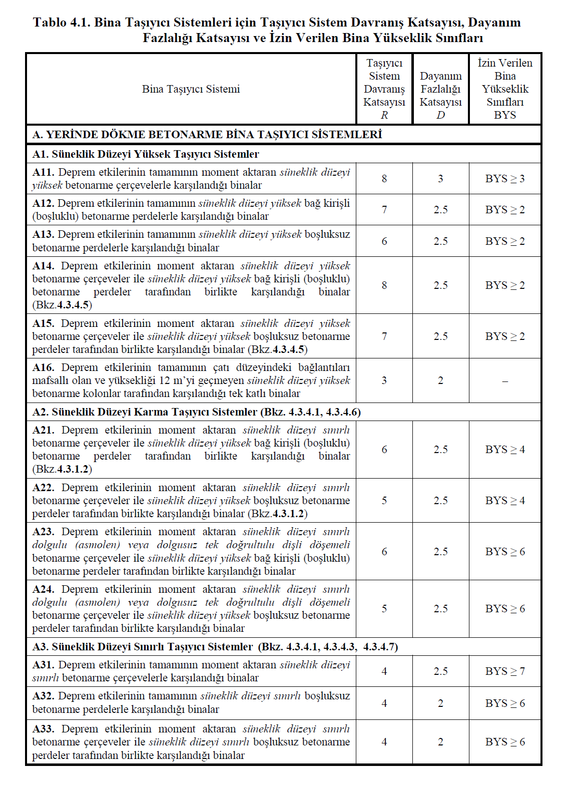
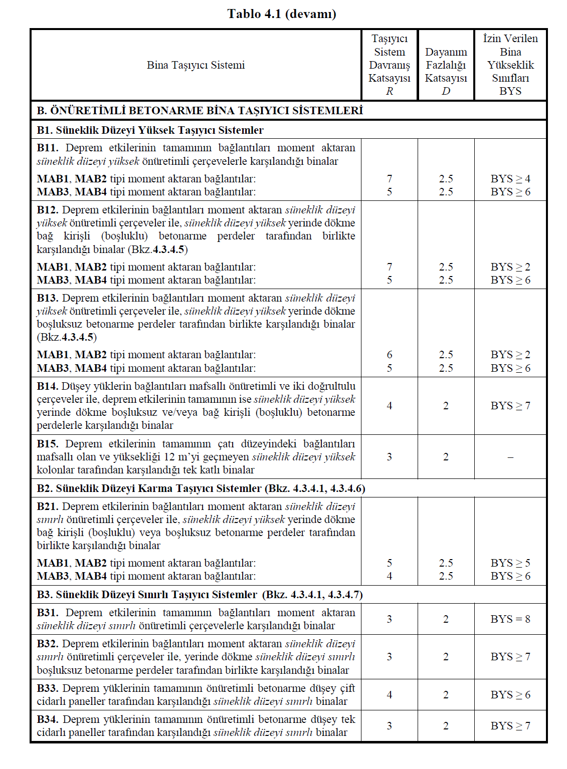
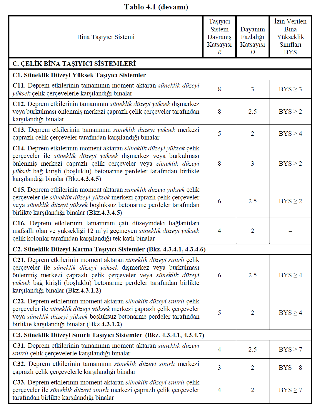
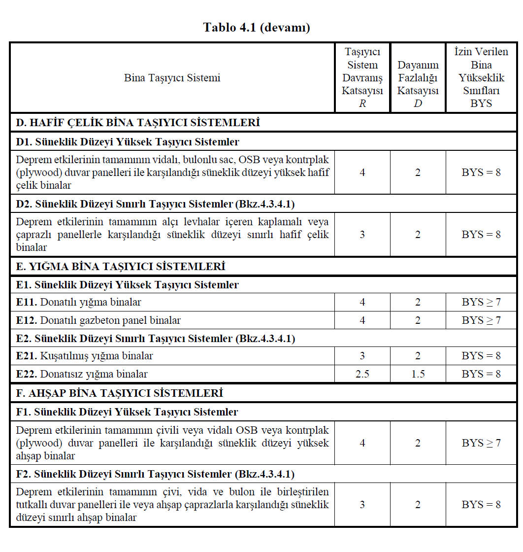
BMS = Building Height Class
DTS = Seismic Design Class
D = Resistance Redundancy Kaysayı of
H w = Curtain height
I = Building Importance Factor
l w = height of the screen's plan
M DEV = reinforced concrete curtain or braced frame at the bottom of the earthquake loads from tilting moments occurring
M o = Building total tipping moment at the base from earthquake loads for all of them
R = Carrier System Behavior Coefficient
4.3.4. Conditions Regarding Ductility Levels of Carrier Systems
4.3.4.1 - Regarding limited ductility level and mixed systems;
(a) Structural systems with limited ductility level cannot be used in buildings classified as DTS = 1a, DTS = 2a, DTS = 3a and DTS = 4a . Other limitations regarding this type of carrier systems are specified in 4.3.4.3 .
(b) In buildings with BYS 6 and classified as DTS = 1a and DTS = 2a, ductility mixed structural systems cannot be used.
4.3.4.2 - The ductility levels of the structural systems in vertical directions to each other must be the same. However, different R coefficients and corresponding D coefficients can be used in perpendicular directions. The highest permitted Building Height Class according to Table 4.1 will be determined as unfavorable for those given in two directions.
4.3.4.3 - transfer torque entire seismic effects ductility of structural systems have been met with limited concrete frame ( Table 4.1 from A31 , B31 , C31 conveyor systems) will be used only in buildings with DTS = 3 and DTS = 4. Filled (filler) or unfilled single-direction geared reinforced concrete frames will also be classified as structural systems with limited ductility level and will only be used in buildings with DTS = 3 and DTS = 4. Such load-bearing systems are reinforced concrete bond beams (hollow) with high ductility level and / or bulkheads or walls with high ductility level.steel eccentric and / or central bracing frames arranged with the composite ductility can be made in the system ( Table 4.1 from A2 , B2 , C2 carrier systems).
4.3.4.4 - Only the conveyor system including without girders floors, all of earthquake effects in concrete buildings ductility level high bond beam (hollow) and / or without curtains or ductility is limited shall be borne by the spaces curtains ( Table 4.1 from the A12 , A13 and A32 conveyor systems) . In steel building ductility high central and / or eccentric braced prevented from buckling or braced frames or ductility limited bracing frames will be used ( Table 4.1 from C12 , C13 andC32 carrier systems). The calculation of such systems will be done in two stages. In the first stage calculation, frame columns will be hinged from the bottom and top. In the second stage calculation, the connections of these elements will be modeled as monolithic. Internal forces in walls, columns, crosses and floors will be calculated as the unfavorable of those obtained in two stages. Relative story offsets will be obtained from the second stage calculation.
4.3.4.5 - high ductility level bond beams (clearance) with or without in-situ or precast center by reinforced concrete walls, eccentric or sprain hindered steel moment resisting frames braced high ductility in buildings is used with the frame at the base of the frame or braced frames tipping consisting of seismic loads The sum of their moments shall not be less than 40% and not more than 75% of the total tipping moment at the base from earthquake loads for the entire building:

If the upper boundary condition in this relation is not fulfilled, the R and D coefficients defined in Table 4.1 for cases where all earthquake effects are met with walls with high ductility level or braced frames and the maximum permissible DMS will be taken into consideration. If the lower limit condition is not fulfilled , the R and D coefficients given in Table 4.1 will not be changed, but one more of the upper permitted IMS will be considered.
4.3.4.6 - concrete and steel ductility in the mixed carrier system, ductility high bond beam (hollow) or center spaces reinforced concrete walls, eccentric or sprain hindered steel at the base of the frame bracing seismic loads from the sum of the tipping moment occurring in the base of the seismic loads for the entire building not less than 75% of the total overturning moment occurred:

If this condition is not fulfilled, the R and D coefficients defined in Table 4.1 for cases where all earthquake effects are met with limited ductility level frames and the maximum permissible IMS will be taken into consideration.
4.3.4.7 - ductility level limited spaces reinforced concrete walls or ductility limited central steel moment resisting frames braced ductility level limited concrete or in buildings is used with steel frame Eq. (4.3) 't given condition will be ensured. Otherwise , the rule given in 4.3.4.6 will be applied.
4.3.4.8 - For use in 4.3.2.4 , 4.3.4.5 and 4.3.4.6 , the base overturning moments M DEV received by the walls are tie-beam according to 4.5.3.7 (d) or 4.5.3.8 (c) for solid walls. For (hollow) curtains, it will be calculated according to 4.5.4.3 . Overturning moment of the earthquake loads occurring for the entire building M o is 4.7 , 4.8.2 or 4.8.3 according would be obtained.
4.3.4.9 - Except for basement perimeter walls, internal forces calculated according to the R coefficients given in Table 4.1 in non-gap walls with H w / l w ≤ 2.0 shall be increased by multiplying by the coefficient [3 / (1+ H w / l w )]. However, this coefficient will not be taken higher than 2.
4.3.4.10 - Rigid reinforced concrete curtains used around the basement floors of buildings will not be considered as part of the curtain or curtain-framed systems in Table 4.1 (See 4.3.5.1 ).
-
Nominal Ductility Level and Mixed Ductility Level (4.3.4.1) -
Structural Systems for Perpendicular Directions (4.3.4.2) -
Ribbed Slab Type Systems (4.3.4.3) -
Structural Systems Including Non-beam Slabs (4.3.4.4) -
Overturning Moment Condition for Shearwalls (4.3.4.5) -
Overturning Moment Condition (0.75) for Shearwalls (4.3.4.6) -
Structural Systems with Nominal Ductiliy Level Shearwall and Moment Frames (4.3.4.7) -
Overturning Moment of Shearwalls (4.3.4.8) -
Shearwall Length of Vertical Wall Segment / Wall Thickness (Hw/lw ≤ 2.0) Condition (4.3.4.9) -
Reinforced Concrete Shearwalls in Basement Stories (4.3.4.10)