
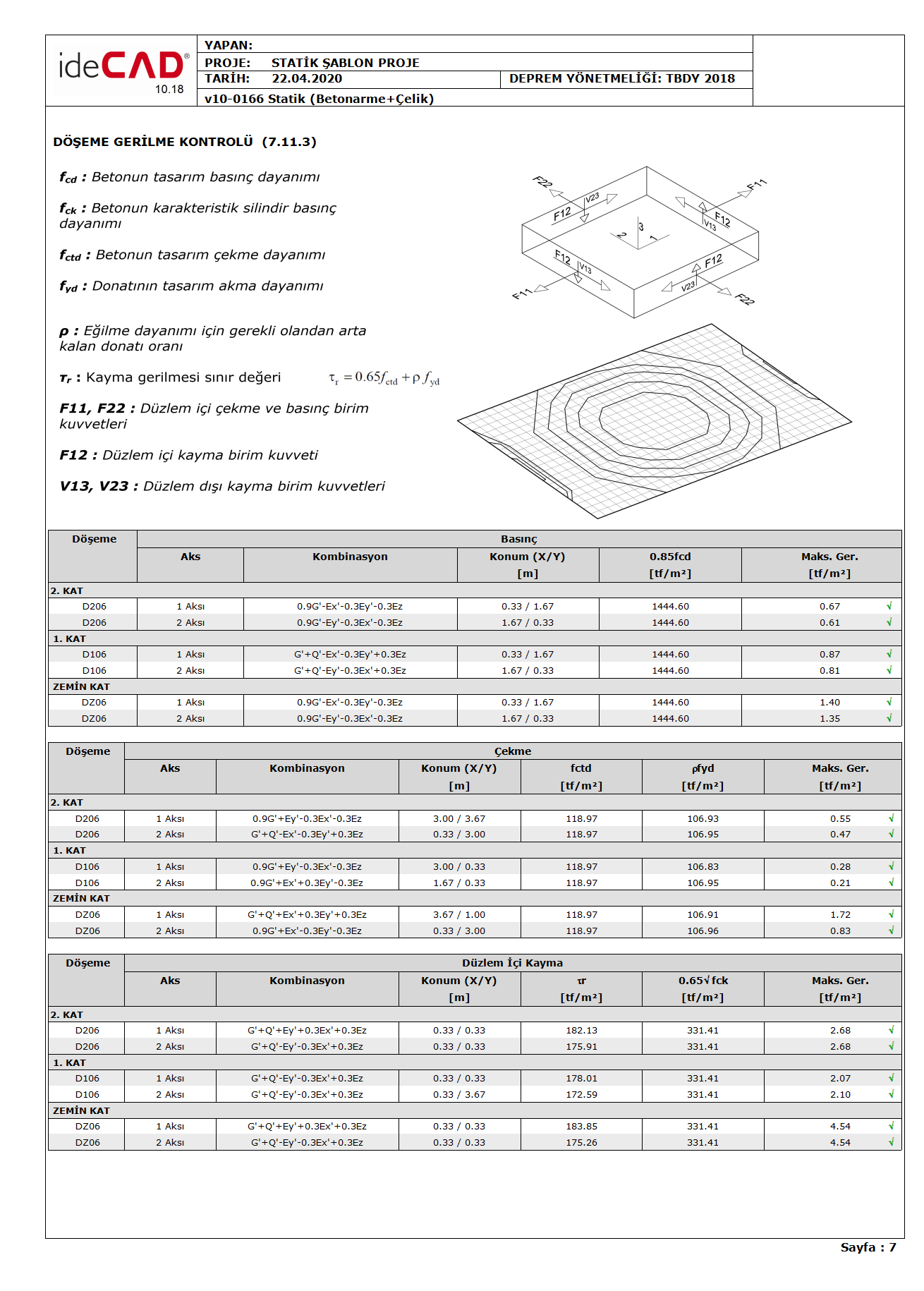
Slab stress control Compressive stress, tensile stress and in-plane shear stress are controlled using shell finite element results in accordance with TBDY Clause 7.11.3. A solution is made with the adoption of semi-rigid diaphragms to find the stresses on the floors of buildings with and without beams. The Strength Excess Coefficient D is applied to the in-plane pressure, tensile and shear stresses of floors caused by earthquakes.
Since the slab stress values are calculated for two main directions according to the local axes, the axis according to which it is calculated is shown under the "Axis" section in the report. The axis defined here is the "slab calculation axis". For example, if "Axle 1" is written under the column "Axis", this number 1 shows the stress value in the direction of the slab calculation axis. This control is made by taking into account all calculation axes defined for the flooring and the reinforcements defined in these calculation axes.
The load combination at which the greatest stress occurs in the slab is shown under the "Combination" column depending on their directions. The stresses resulting from these load combinations are calculated by applying the Strength Excess Coefficient D of the earthquake effects together with the vertical loads.
The location where the greatest stress occurs in the slab is specified under the "Position (X / Y)" column in the report. This location is defined on the global axis with relevant values.
Pressure Stress Control
With the semi-rigid diaphragm solution, the in-plane compressive stresses in floors are obtained from the F11 and F22 results calculated under the combined effect of the earthquake loads calculated by taking into account the vertical loads multiplied by the load coefficients and the Strength Excess Coefficient D.
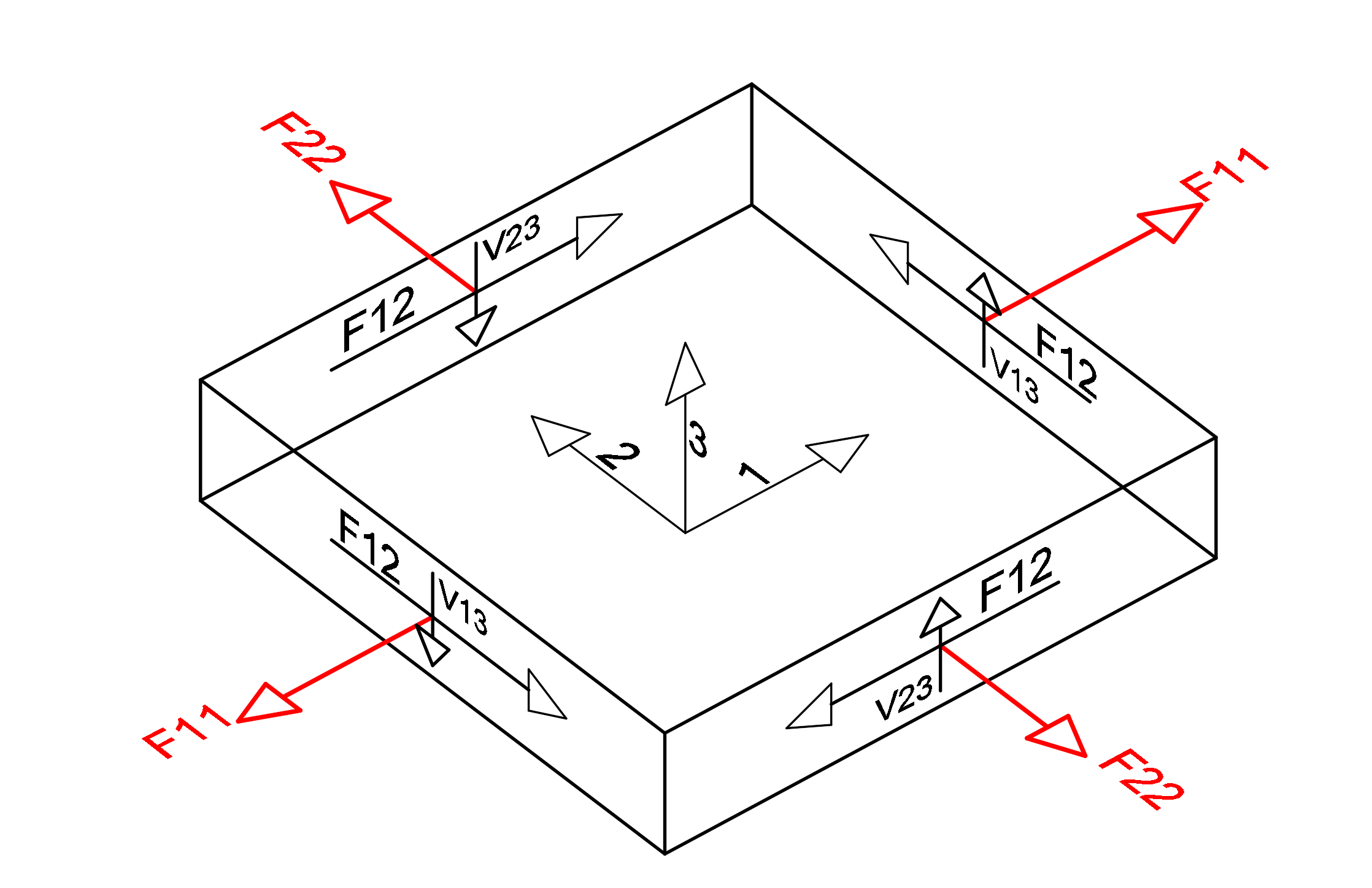
F11 and F22 are the forces that are parallel to the floor plane and perpendicular to the slab edges that are formed in the direction of 1 and 2, respectively, according to the local axes of the elements (floor and curtain) modeled with shell finite elements. If these forces are negative (-), this force is the pressure force. When these values (F11 and F22) are divided by the slab thickness, the in-plane pressure stresses occurring in the slab are found.
The image below shows the local axes of a finite element and a free body diagram. The unit length forces in the finite element in the middle of this finite element with respect to the local axis directions indicated by 1,2,3 are shown. F11 and F22 values are shown in red. In the compressive stress control, the F11 and F22 values calculated according to the local axis of the element are divided by the slab thickness and the compressive stress value formed in the finite element is found.
The greatest compressive stress in the slab shall not exceed the limit of 0.85f cd according to Article 7.11.3 of TBDY .
f cd is the design compressive strength of concrete. In this control, the reinforcement has no effect since the limit value is determined only by the concrete class.
Tensile Stress Control
With the semi-rigid diaphragm solution, the in-plane tensile stresses in floors are obtained from the F11 and F22 results calculated under the combined effect of the earthquake loads calculated by taking into account the vertical loads multiplied by the load coefficients and the Strength Excess Coefficient D.
F11 and F22 are forces that are parallel to the floor plane and perpendicular to the slab finite element edges that are formed in 1 and 2 directions, respectively, according to the local axes of the elements (floor and curtain) modeled with shell finite elements. If these forces are positive (+), this force is the pulling force. When these values (F11 and F22) are divided by the slab thickness, the in-plane tensile stresses occurring in the slab are found.
The image below shows the local axes of a finite element and a free body diagram. The unit length forces in the finite element in the middle of this finite element with respect to the local axis directions indicated by 1,2,3 are shown. F11 and F22 values are shown in red. In the tensile stress control, the F11 and F22 values calculated according to the local axis of the element are divided by the slab thickness and the tensile stress value formed in the finite element is found.
According to Article 7.11.3 of TBDY , in cases where the tensile stress occurring in the slab plane is greater than the design tensile stress f ctd of the concrete , the yield strength of the remaining reinforcement ρf than required for the flexural strength of the slab should not exceed yd . Determine the yield strength of the remaining reinforcement ρf yd from what is required for the flexural strength of the slab, with the ratio ρ of the remaining reinforcement required for the bending strength and the design yield stress f yd of the slab reinforcement. equals the product.
Since the design tensile strength f ctd of concrete is very small compared to the design compressive strength f cd of the concrete , the slab tensile stress is mostly borne by the slab reinforcement. For this reason, local floors should be defined in areas where tensile stress is high, and appropriate reinforcements should be placed in a way that takes into account the slab calculation axes.
Shear Stress Control
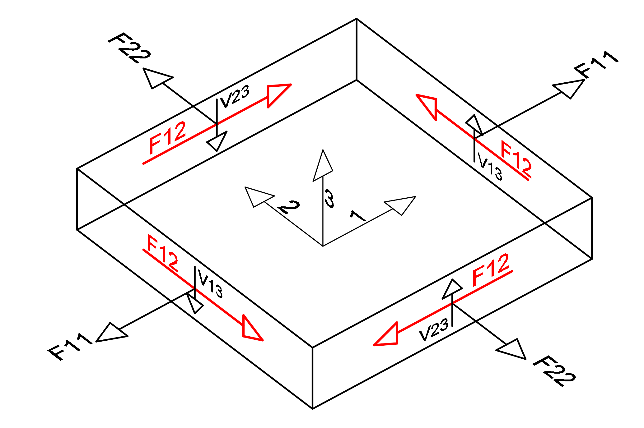
With the semi-rigid diaphragm solution, the in-plane shear stresses in floors are obtained from the F12 results calculated under the combined effect of the earthquake loads calculated by considering the vertical loads multiplied by the load coefficients and the Strength Excess Coefficient D.
F12 is the shear force of the shell finite element calculated in the plane and occurring in unit length. This value has equal value on all surfaces of the shell finite element and is shown in red in the picture below. The in-plane shear stress value is obtained by dividing the F12 value by the slab thickness.
TBDY Article 7.11.3 according ρ bending residual than required for recovery and parallel to the shear stresses
that will be placed in the direction slab reinforcement ratio, f yd design yield stress of slab reinforcement and f ctd concrete design tensile strength, including horizontal shear stress in the plane of laying TBDY It shall not exceed the limit value given by Equation 7.25 .
In this equation, part of the shear stress is covered by the concrete and the other part by the reinforcement. Defining additional reinforcements in regions with high in-plane shear stress or defining local slabs and changing the amount of reinforcement is a sufficient solution to achieve this value. However, the upper limit value of the slab in-plane shear stress is defined as 0.65 (f ck ) 1/2 . If the in-plane shear stress of the slab exceeds this value, a carrier system should be placed to increase the slab thickness or reduce the stress.
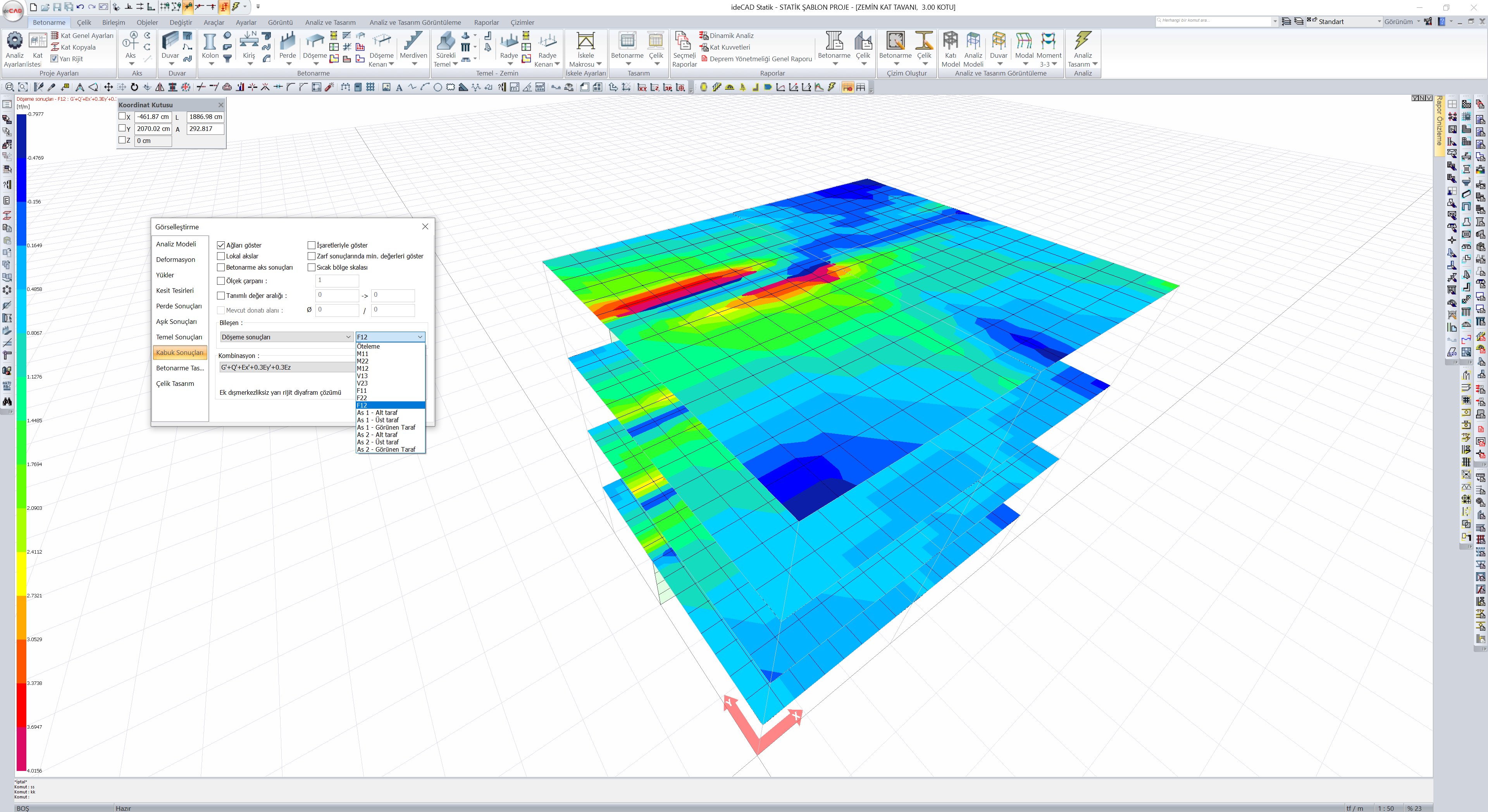
Reading F11, F22 and F12 values
F11, F22 and F12 values can be viewed with the "Shell Results" tab from the window opened after opening the right click menu and clicking on the "Analysis system display options" command.
Next Topic
Related Topics