
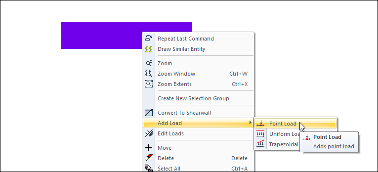
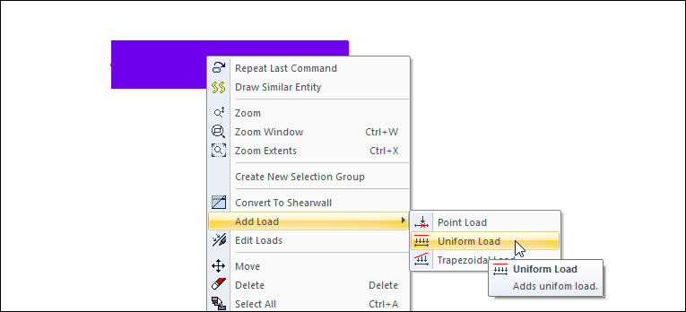
After selecting the element you want to define external load on the plan window, click the right mouse button on the element.
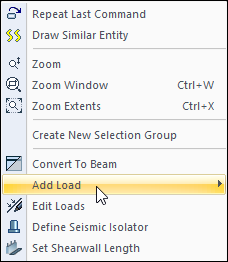
In the menu that opens, you can define the loads with the size and geometry you want by using the options under the heading add load.
Defining External Loads to Columns
Point Load Definition
-
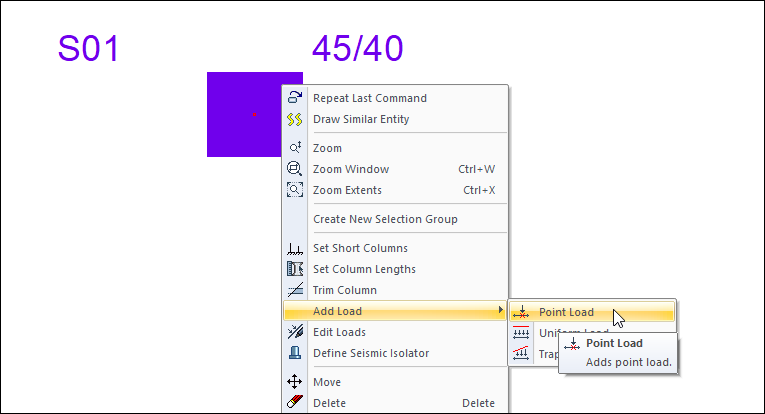
Select the column for which you want to define point load from the plan window.
-
Press the right mouse button on the column.
-
From the menu that opens, go to the Add Load line and click the Point Load line from the sub menu.
-
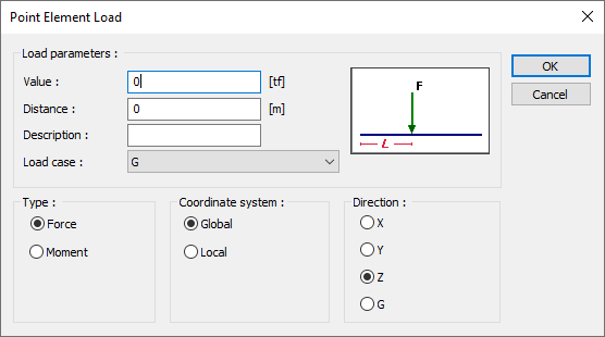
You will see the Point Element Loads dialog.
-
Enter the size of the load in the Value section.
-
In the Distance field, enter the distance of the load from the lower end of your column.
-
Enter the description of the load and the load case.
-
Enter the type, coordinate system and direction.
-
Press the OK button to exit the dialog.
|
Specifications |
|---|
|
Value (F) Enter the value of the load in the working unit. |
|
Distance (L) Give the distance value for the load. |
|
Description Write the description of the load that you will describe. |
|
Load case From the list, select the loading state to which the load you define will apply. If the installation conditions are not defined in the system, the program will ask you to define it. |
|
Type 
Check the option Moment if the specified load is moment, or force if the force. |
|
Coordinate system 
Specify whether the entered load values are given relative to the element local axes or relative to global axes. |
|
Direction Give information in which direction the load is valid. Shows the direction of the load according to the X, Y, Z global coordinate system, 1, 2, 3 local coordinate axes. G indicates that this load is a constant (vertical) load. |
Uniform Load Definition
-
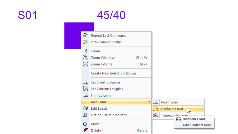
Select the column for which you want to define a uniform load from the plan window.
-
Press the right mouse button on the column.
-
From the menu that opens, go to the Add Load line and click the Uniform Load line from the submenu .
-
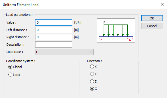
You'll see the Uniform Element Load dialog.
-
Enter the size of the load in the Value section.
-
In the left and right distance boxes, enter the starting distances of the load to the upper and lower ends of your column.
-
Write the description of the load in the description box.
-
Select the load case, coordinate system and direction.
-
Press the OK button to exit the dialog.

|
Specifications |
|---|
|
Value (F) Enter the value of the load in the working unit. |
|
Left distance (L) Give the distance value to the lower end for vertical elements and to the left end for horizontal elements. |
|
Right distance (R) Give the distance value with respect to the upper end in vertical elements and to the right end in horizontal elements. |
|
Description Write the description of the load that you will describe. |
|
Load case From the list, select the loading state to which the load you define will apply. If the installation conditions are not defined in the system, the program will ask you to define it. |
|
Coordinate system
Specify whether the entered load values are given relative to the element local axes or relative to global axes. |
|
Direction Give information in which direction the load is valid. Shows the direction of the load according to the X, Y, Z global coordinate system, 1, 2, 3 local coordinate axes. G indicates that this load is a constant (vertical) load. |
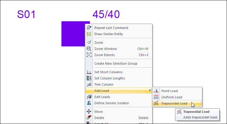
Trapezoidal Load Definition
-
Select the column for which you want to define trapezoidal load from the plan window.
-
Press the right mouse button on the column.
-
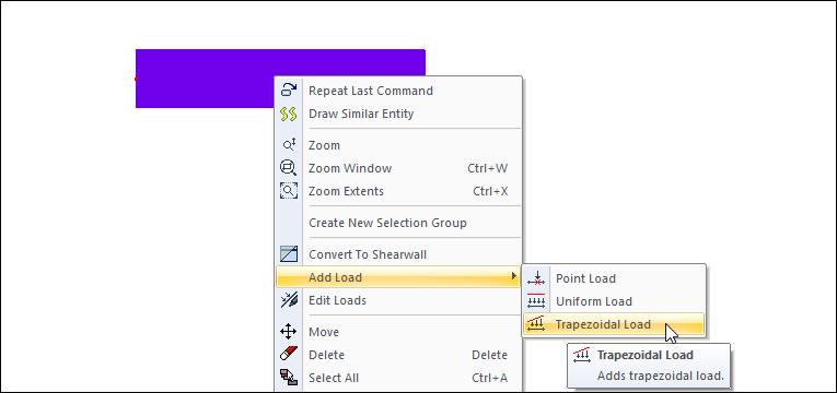
From the menu that opens, go to the Add Load line and click the Trapezoidal Load line from the submenu.
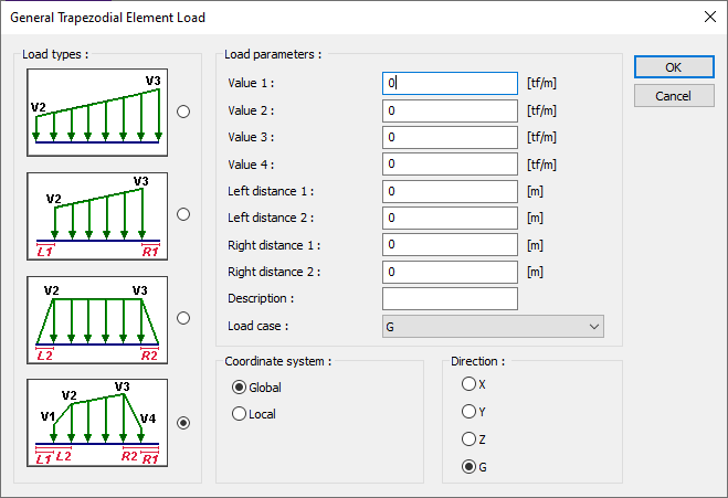
-
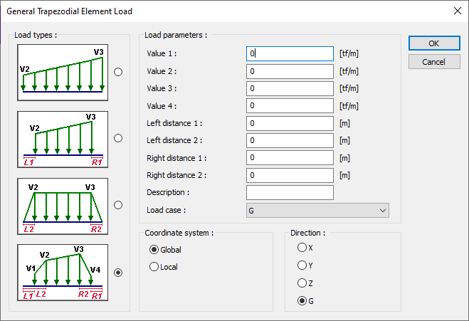
You will see the General Trapezoidal Element Load dialog.
-
In the load type box, tick the option appropriate to the geometry of your load.
-
Write the load values and distances in the boxes that are active according to the option you selected.
-
Write the description of the load in the description box.
-
Select the upload state, coordinate system and direction.
-
Press the OK button to exit the dialog.
|
Specifications |
|---|
|
Load types 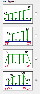
Choose the type of load. |
|
Value 1, Value 2, Value 3, Value 4, (V1, V2, V3, V4) 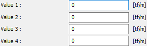
Enter the value of the load in working unit. |
|
Left distance 1, Left distance 2 (L1, L2) Give the distance values relative to the lower end for vertical elements and to the left end for horizontal elements. |
|
Right distance 1, Right distance 2 (R1, R2) Give the distance values relative to the upper end in vertical elements and to the right end in horizontal elements. |
|
Description Write the description of the load that you will describe. |
|
Load case From the list, select the loading state to which the load you define will apply. If the installation conditions are not defined in the system, the program will ask you to define it. |
|
Coordinate system
Specify whether the entered load values are given relative to the element local axes or relative to global axes. |
|
Direction Give information in which direction the load is valid. Shows the direction of the load according to the X, Y, Z global coordinate system, 1, 2, 3 local coordinate axes. G indicates that this load is a constant (vertical) load. |
Defining Loads to Shearwalls
In order to define vertical and lateral areal loads on the shearwalls, the shearwalls should be modeled as shells.
Vertical Load Definition
-
Model your shearwalls as shell elements.
-
Select the shearwalls you want to define vertical load on from the plan window.
-
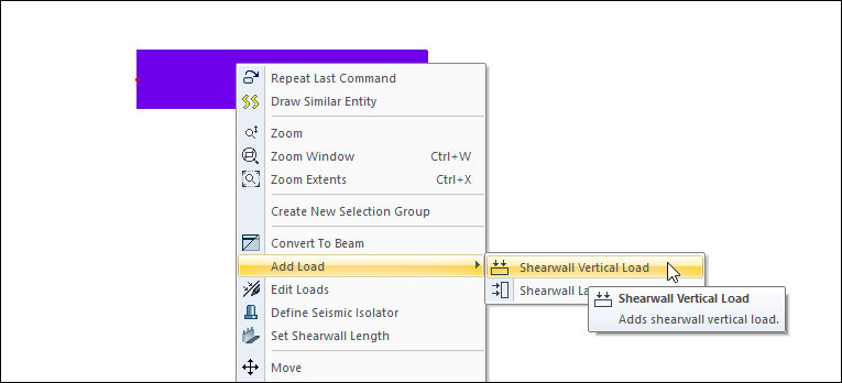
Press the right mouse button on the shearwalls.
-
From the menu that opens, go to the Add Load line and click the Shearwall Vertical Load line from the submenu.
-
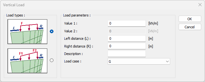
You will see the Vertical Load dialog.
-
In the load type box, tick the option appropriate to the geometry of your load.
-
Write the load values and distances in the boxes that are active according to the option you selected.
-
Write the description of the load in the description box.
-
Choose the load case.
-
Press the OK button to exit the dialog.
|
Specifications |
|---|
|
Load type 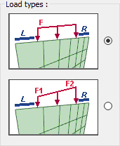
Choose the type of load. |
|
Value 1, Value 2 (F1, F2) Enter the value of the load in working unit. |
|
Left distance (L) Give the distance value to the lower end for vertical elements and to the left end for horizontal elements. |
|
Right distance (R) Give the distance value with respect to the upper end in vertical elements and to the right end in horizontal elements. |
|
Description Write the description of the load that you will describe. |
|
Load case From the list, select the loading state to which the load you define will apply. If the installation conditions are not defined in the system, the program will ask you to define it. |
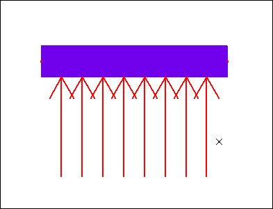
Lateral Load Definition
-
Model your shearwalls as shell elements.
-
Select the shearwall you want to define a lateral load from the plan window.
-
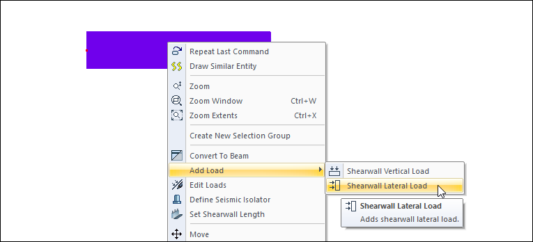
Press the right mouse button on the shearwall.
-
Go to the Add Load line from the menu that opens and click the Shearwall Lateral Load line from the submenu.
-
Move your mouse in the plan window to determine the direction of action of the lateral load and press the left mouse button.
-
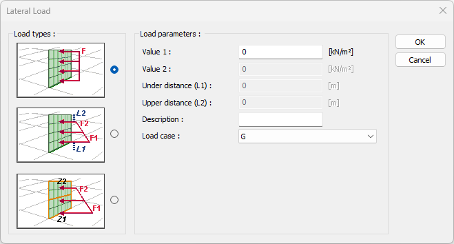
You will see the Shearwall Lateral Load dialog.
-
In the load type box, tick the option appropriate to the geometry of your load.
-
Write the load values and distances in the boxes that are active according to the option you selected.
-
Write the description of the load in the description box.
-
Choose the load case.
-
Press the OK button to exit the dialog.
|
Specifications |
|---|
|
Load type 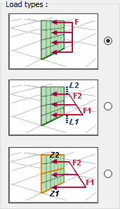
Choose the type of load. |
|
Value 1, Value 2 (F1, F2) Enter the value of the load in working unit. |
|
Under distance (L1) Give the distance value with respect to the under of the element. |
|
Upper distance (L2) Give the distance value with respect to the upper of the element. |
|
Under elevation (Z1) Under elevation value of the load. While editing this value, the story levels determined in the Story Settings should be taken as basis. |
|
Upper elevation (Z2) Upper elevation value of the load. While editing this value, the story levels determined in the Story Settings should be taken as basis. |
|
Description Write the description of the load that you will describe. |
|
Load case From the list, select the loading state to which the load you define will apply. If the installation conditions are not defined in the system, the program will ask you to define it. |
Defining External Loads to Beams
Point Load Definition
-
Select the beam for which you want to define point load from the plan window.
-
Press the right mouse button on the beam.
-
From the menu that opens, go to the Add Load line and click the Point Load line from the submenu.
-
You will see the Point Element Load dialog.
-
Enter the size of the load in the Value section.
-
In the Distance field, enter the distance of your load from the lower end of your column.
-
Enter the description of the load and the load case.
-
Enter the load type, coordinate system and direction.
-
Press the OK button to exit the dialog.

|
Specifications |
|---|
|
Value (F) Enter the value of the load in the working unit. |
|
Distance (L) Give the distance value for the load. |
|
Description Write the description of the load that you will describe. |
|
Load case From the list, select the loading state to which the load you define will apply. If the installation conditions are not defined in the system, the program will ask you to define it. |
|
Type
Check the option Moment if the specified load is moment, or force if the force. |
|
Coordinate system
Specify whether the entered load values are given relative to the element local axes or relative to global axes. |
|
Direction Give information in which direction the load is valid. Shows the direction of the load according to the X, Y, Z global coordinate system, 1, 2, 3 local coordinate axes. G indicates that this load is a constant (vertical) load. |
Uniform Load Definition
-
Select the beam for which you want to define a uniform load from the plan window.
-
Press the right mouse button on the beam.
-
From the menu that opens, go to the Add Load line and click the Uniform Load line from the submenu.
-
You'll see the Uniform Element Load dialog.
-
Enter the size of the load in the Value section.
-
In the left and right distance boxes, enter the starting distances of the load to the upper and lower ends of your beam.
-
Write the description of the load in the description box.
-
Select the load case, coordinate system and direction.
-
Press the OK button to exit the dialog.
|
Specifications |
|---|
|
Value (F) Enter the value of the load in the working unit. |
|
Left distance (L) Give the distance value to the lower end for vertical elements and to the left end for horizontal elements. |
|
Right distance (R) Give the distance value with respect to the upper end in vertical elements and to the right end in horizontal elements. |
|
Description Write the description of the load that you will describe. |
|
Load case From the list, select the loading state to which the load you define will apply. If the installation conditions are not defined in the system, the program will ask you to define it. |
|
Coordinate system
Specify whether the entered load values are given relative to the element local axes or relative to global axes. |
|
Direction Give information in which direction the load is valid. Shows the direction of the load according to the X, Y, Z global coordinate system, 1, 2, 3 local coordinate axes. G indicates that this load is a constant (vertical) load. |
Trapezoidal Load Definition
-
Select the beam for which you want to define a trapezoidal load from the plan window.
-
Press the right mouse button on the beam.
-
From the menu that opens, go to the Add Load line and click the Trapezoidal Load line from the submenu.
-
You will see the General Trapezoidal Element Load dialog.
-
In the load type box, tick the option appropriate to the geometry of your load.
-
Write the load values and distances in the boxes that are active according to the option you selected.
-
Write the description of the load in the description box.
-
Select the load case, coordinate system and direction.
-
Press the OK button to exit the dialog.
|
Specifications |
|---|
|
Load types
Choose the type of load. |
|
Value 1, Value 2, Value 3, Value 4, (V1, V2, V3, V4)
Enter the value of the load in working unit. |
|
Left distance 1, Left distance 2 (L1, L2) Give the distance values relative to the lower end for vertical elements and to the left end for horizontal elements. |
|
Right distance 1, Right distance 2 (R1, R2) Give the distance values relative to the upper end in vertical elements and to the right end in horizontal elements. |
|
Description Write the description of the load that you will describe. |
|
Load case From the list, select the loading state to which the load you define will apply. If the installation conditions are not defined in the system, the program will ask you to define it. |
|
Coordinate system
Specify whether the entered load values are given relative to the element local axes or relative to global axes. |
|
Direction Give information in which direction the load is valid. Shows the direction of the load according to the X, Y, Z global coordinate system, 1, 2, 3 local coordinate axes. G indicates that this load is a constant (vertical) load. |
Changing and Deleting Loads Defined to Elements
In order to change the properties of the entered loads;
-
Select the element whose load you want to change from the plan window.
-
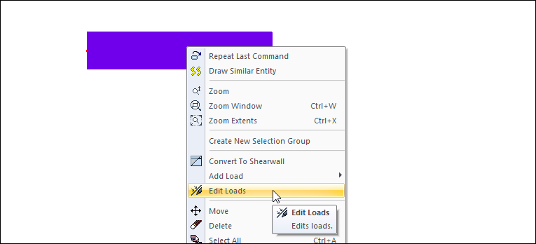
Press the right mouse button on the element.
-
From the menu that opens, click on the Edit Loads line.
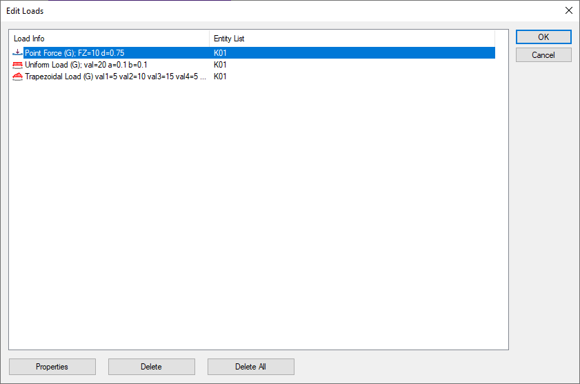
-
The Edit Loads dialog will appear.
-
Select the load you want to change from the list and click the Properties button.
-
The load setting dialog will appear. Organize your load here.
-
Press OK to exit dialogs
In order to delete the loads entered;
-
Select the element whose load you want to delete from the plan window.
-
Press the right mouse button on the element.
-
From the menu that opens , click on the Edit Loads row.
-
The Edit Loads dialog will appear.
-
Select the load you want to delete from the list and click the Delete button.
-
Press OK to exit the dialog. Your load will be deleted.
Analysis of Added Loads from Analysis Model
In order to see the loads you defined on columns and beams;
-
Press the right mouse button in the perspective window.
-
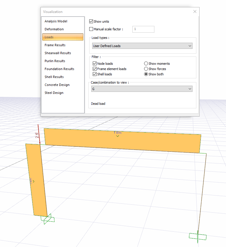
Click the Analysis System line in the menu that opens. The visualization dialog will appear.
-
In the Loads tab, click the Load type list.
-
Click the User Defined Loads line of the load types.
-
Check the option appropriate to the load you defined from the combination.
-
Your loads will appear on the elements.
In order to see the loads defined on shearwalls;
-
Press the right mouse button in the perspective window.
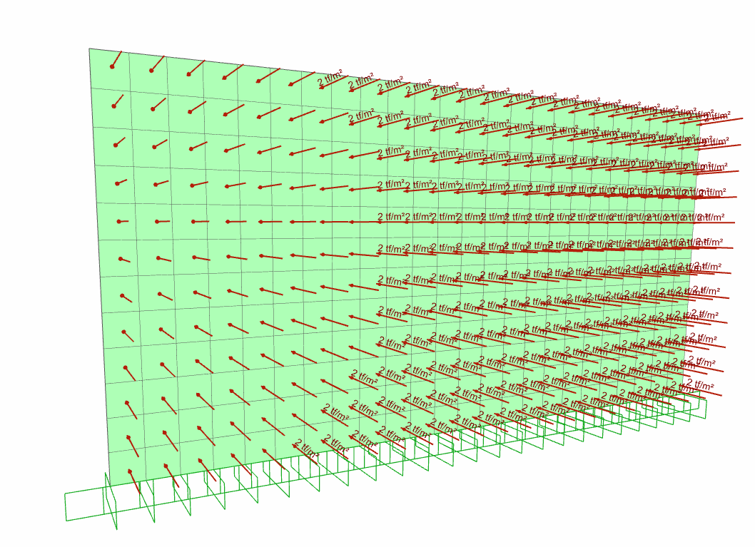
-
In the menu that opens, click the Structural Visualization Option line. The visualization dialog will appear.
-
Click the Loads tab.
-
Click the Load type line from the load types .
-
Select the option appropriate for the load you defined from the loading cases.
-
Your loads will appear on the elements.
Analysis of Added Loads from Reports
In order to see the loads you defined on columns and beams in reports;
-
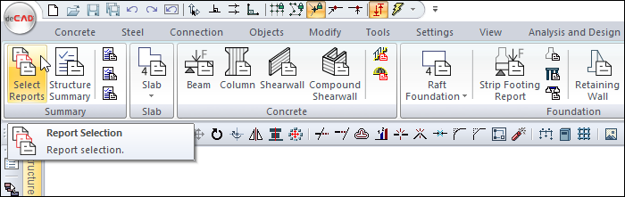
From the Reports tab Summary heading, click the Report Selection icon.
-
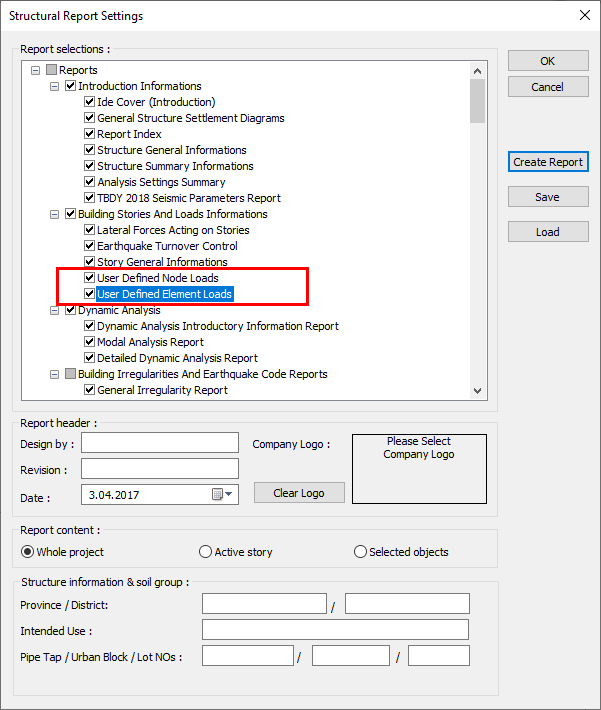
Come to the end of the list in the Structural Report Settings dialog that comes up.
-
Activate the User Defined Node Loads and User Defined Element Loads options under the Building Stories and Load Information option.
-
Create the report. At the end of the reports, the information of the loads you defined will be printed.
User loads defined on shearwalls in the program cannot be displayed in reports.
Related Topics