
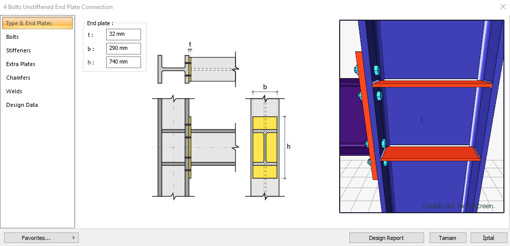
4 bolt unstiffened end plate connection is a moment-resisting connection (rigid connection) that is connected to the columns' flange to the beams. Bolt control, weld control, plate control and connection application limits control are performed automatically according to the placement of the elements of the connection. 4 bolt unstiffened end plate connection is made automatically according to the Design, Calculation and Construction Principles of Steel Structures (ÇYTHYEDY) or AISC 360-16 regulations and the connection report is generated. Connection detail application limits are checked according to TBDY Table 9B.1.
In the calculation of the connection, the horizontal and vertical bolt distances, end plate weld thickness, continuity plate weld thickness and application limits are checked under geometry control. In strength checks, bolt diameter, end plate thickness, end plate shear yield, end plate shear failure, etc. are checked and reported.
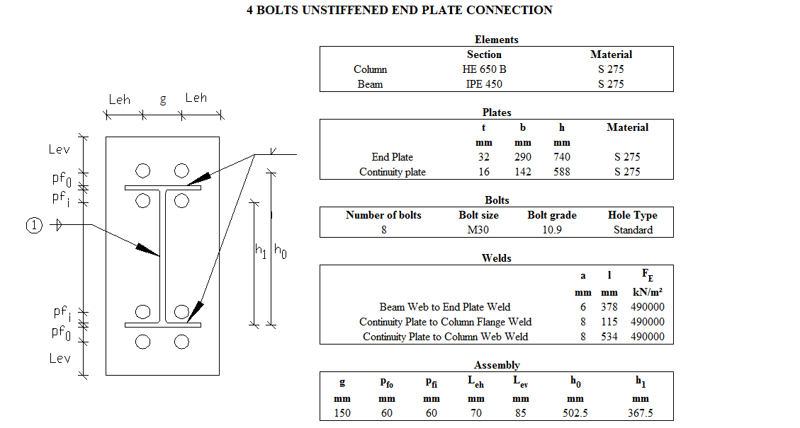
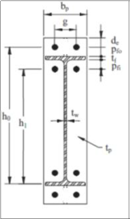
Connection Geometry
Geometry Checks
Horizontal Edge Distance
|
|
ÇYTHYEDY 13.3.7 |
|
|
|
|
70 mm |
L eh ≥ 2d = 2 * 30 = 60 mm conformity check for application |
√ |
|
|
40 mm |
Minimum distance check according to Table 13.9 |
√ |
Vertical Edge Distance
|
|
ÇYTHYEDY 13.3.7 |
|
|
|
|
85 mm |
L eh ≥ 2d = 2 * 30 = 60 mm conformity check for application |
√ |
|
|
40 mm |
Minimum distance check according to Table 13.9 |
√ |
Beam Web to End Plate Weld Size
|
|
|
|
|
|
|
6 mm |
|
√ |
|
|
3.5 mm |
Table 13.4 |
√ |
Continuity Plate to Column Flange Weld Size
|
|
|
|
|
|
|
8 mm |
|
√ |
|
|
4 mm |
Table 13.4 |
√ |
Continuity Plate to Column Web Weld Size
|
|
|
|
|
|
|
8 mm |
|
√ |
|
|
4 mm |
Table 13.4 |
√ |
Connection Detail Prequalification Limits (TBDY Table 9B.1)
|
Beam span / Beam cross-section height |
9144 mm /450 mm=20.32 |
≥7.0 |
|
End plate thickness, tp |
32 mm |
12≤t p ≤60 |
|
Head plate width, bp |
290 mm |
160≤ b p ≤ 300 |
|
Horizontal distance between bolts, g |
150 mm |
100≤g≤155 |
|
pfi |
60 mm |
40≤p fi ≤115 |
|
pfo |
60 mm |
40 p fo ≤115 |
|
Beam cross-section height, db |
450 mm |
270≤ d b ≤ 1400 |
|
Beam flange thickness, tbf |
15 mm |
10≤t bf ≤25 |
|
Column cross-section height |
650 |
≤ 920 mm |
|
Bolt class |
10.9 |
8.8 - 10.9 |
|
Min yield stress of the end plate material |
275 MPa |
235 /275 / 355 MPa |
|
Flange plate welding |
CJP |
CJP |
Strength Checks
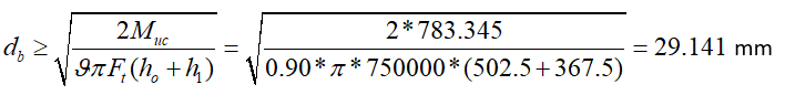
Bolt diameter
|
|
783.345 kNm |
AISC 358-16 (6.8-3) |
|
|
750000 kN/m2 |
|
|
|
|
|
|
x1 |
|
|
|
|
|
|
|
Required |
Ready |
Ratio |
Control |
|---|---|---|---|
|
29.141 mm |
30 mm |
0.971 |
√ |
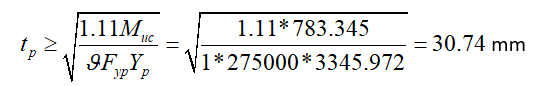
End Plate Thickness
|
|
783.345 kNm |
AISC 358-16 (6.8-5) |
|
|
275000 kN/m2 |
|
|
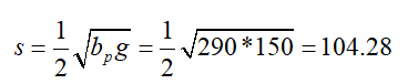
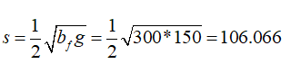
s |
|
|
|
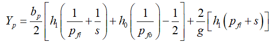
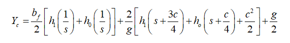
Yp |
|
|
|
Yp |

|
|
|
tp |
|
|
|
Required |
Available |
Ratio |
Control |
|---|---|---|---|
|
30.74 mm |
32 mm |
0.961 |
√ |
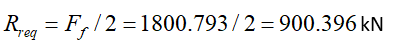
End Plate Shear Yield
|
|
783.345 kNm |
AISC 358-16 (6.8-7) |
|
|

|
|
|
|
|
|
|
|
275000 kN/m2 |
|
|
|
290 mm |
|
|
|
32 mm |
|
|
d |
450 mm |
|
|
|
15 mm |
|
|
|
|
|
|
Required |
Available |
Ratio |
Control |
|---|---|---|---|
|
900,396 kN |
1531.2 kN |
0.588 |
√ |
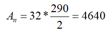
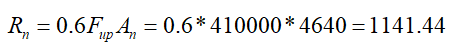
End Plate Shear Rupture
|
|
783.345 kNm |
AISC 358-16 (6.8-7) |
|
|
|
|
|
|
|
|
|
Fup |
410000 kN/m2 |
|
|
|
|
|
|
d |
450 mm |
|
|
|
15 mm |
|
|
|
|
|
|
|
|
|
|
Required |
Available |
Ratio |
Control |
|---|---|---|---|
|
900,396 kN |
1027.3 kN |
0.876 |
√ |
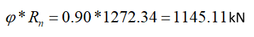
Bolt Shear at Support
|
|
|
|
|
|
|
|
|
|
|
|
|
Required |
Available |
Ratio |
Control |
|---|---|---|---|
|
212.57 kN |
1145.11 kN |
0.186 |
√ |
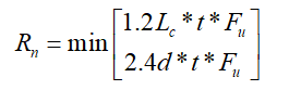
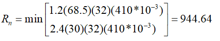
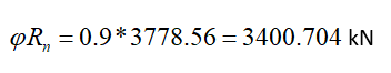
Bolt Bearing on End Plate
|
|
30+3=33 mm |
|
|
|
|
|
|
|
|
ÇYTHYEDY 13.3.13 Equation 13.14a and13.14b |
|
|
|
|
|
|
|
|
|
|
|
|
|
|

|
|
|
|
|
|
|
Required |
Available |
Ratio |
Control |
|---|---|---|---|
|
212.57 kN |
3400.704 kN |
0.063 |
√ |
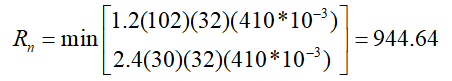
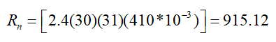
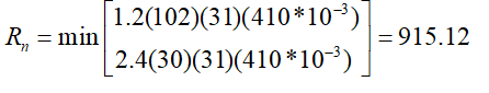
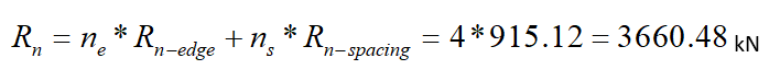
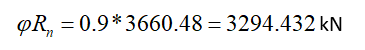
Bolt Bearing on Column Flange
|
|
30+3=33 mm |
|
|
|
|
ÇYTHYEDY 13.3.13 Equation 13.14a and13.14b |
|
|
|
|
|
|
|
|
|
|
|
|
|
|
|
|
|
|
|
|
|
Required |
Available |
Ratio |
Control |
|---|---|---|---|
|
212.57 kN |
3294.432 kN |
0.065 |
√ |
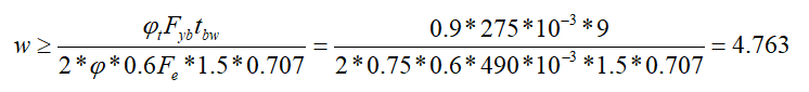
Beam Web to End Plate Weld Strength
|
|
275000 kN/m2 |
AISC 358-16 (6.7.6) 3 |
|
|
9 mm |
|
|
|
490000 kN/m2 |
|
|
w |
|
|
|
Required |
Available |
Ratio |
Control |
|---|---|---|---|
|
4.763 mm |
8.487 mm |
0.561 |
√ |
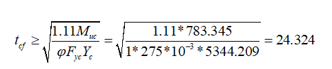
Column Flange Thickness
|
|
783.345 kNm |
AISC 358-16 (6.8-5) |
|
|
275000 kN/m2 |
|
|
s |
|
|
|
c |
|
|
|
Yc |
|
|
|
Yc |

|
|
|
|
|
|
|
Required |
Available |
Ratio |
Control |
|---|---|---|---|
|
24.324 mm |
31 mm |
0.785 |
√ |
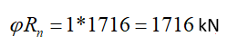
Column Panel Zone Shear
|
|
429.124 kN |
ÇYTHYEDY 13.29a |
|
|
|
|
|
|
275000 kN/m2 |
|
|
|
28634.759 mm2 |
|
|
|
650 mm |
|
|
|
16 mm |
|
|
|

|
|
|
|
|
|
|
Required |
Ready |
Ratio |
Control |
|---|---|---|---|
|
1595.191 kN |
1716 kN |
0.930 |
√ |
Panel Zone Thickness
|
tmin ≥u / 180 |
|
TBDY 2018 9.3.4.2b |
|
tmin = tw |
16 mm |
|
|
|
16 mm |
|
|
u |
2016 mm |
|
|
Required |
Available |
Ratio |
Control |
|---|---|---|---|
|
11.2 mm |
16 mm |
0.700 |
√ |
Next Topic