
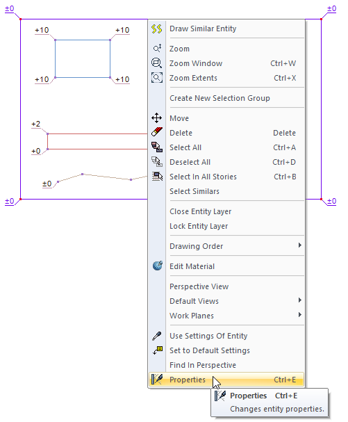
Settings such as terrain detailing, terrain drawing and material selection of the current terrain are accessed with the Properties command. Settings for sub-objects in the modeled terrain are also included in the Terrain Settings dialog.
Location of the Terrain Settings Dialog
Select the terrain you want to enter its settings, click the right button of the mouse and click the Properties line from the menu that opens .
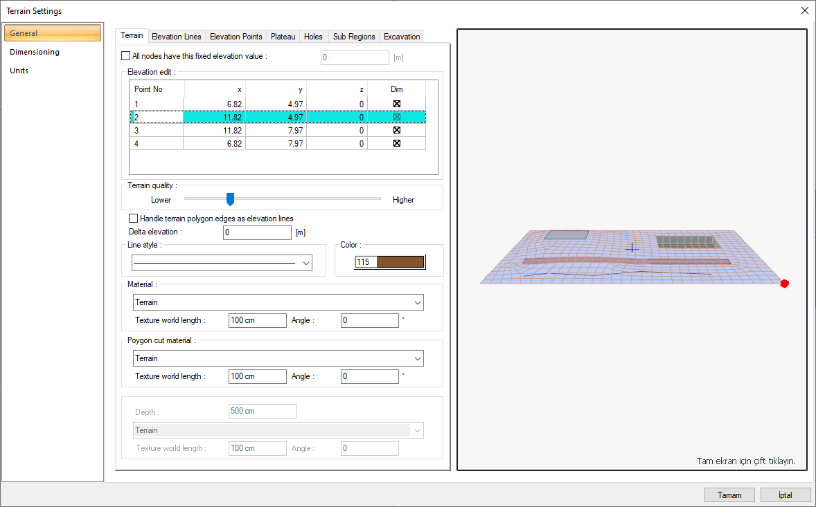
General Tab - Terrain
|
Specifications |
|---|
|
Elevation edit 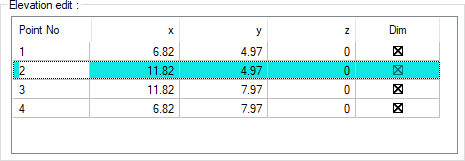
The coordinates of the elevation points placed are given. If wanted, a new value can be entered in the z box. |
|
All nodes have this fixed elevation value The feature is activated and the value entered here is applied to all elevation points. |
|
Terrain quality It is the indicator that determines the detail level of the terrain. A more detailed terrain drawing is created with the pointer drawn from left to right. You can adjust the pointer to a level that will give the optimum performance according to the hardware power of your computer. |
|
Handle terrain polygon edges as elevation lines It linearizes the slopes of the terrain lines whose elevation is between different nodes. |
|
Delta elevation The elevation delta value shifts all elements of the terrain to the global coordinate base. When this value is given as zero, the joint elevations represent the height values based on the global base point. When a value other than zero is entered, the elevation values are shifted relative to the entered value. For example +5.00 m. At the end of the given shift value, the elevation value whose elevation is +2.00 m, +7.00; The elevation value of -1.00 is calculated as +4.00. |
|
Line style Line type of the terrain in the plan is selected. Clicking the down arrow buttons to the right of the boxes opens the list of line types. From this list, the wanted line type is selected by clicking with the left mouse button. |
|
Color It is the drawing color of the land line in the plan. When the color box is clicked, the appropriate color is selected from the window that opens. |
|
Material You can select the material of the land top surface from the list by clicking. |
|
Polygon cut material You can select the material of the cut surfaces from the list by clicking. |
|
Soil 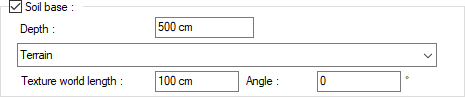
You can select the soil base material from the list by clicking it. The soil base gains depth as much as the value entered in the depth division. |
|
Texture world length Texture length is entered. For example; If 1 meter is entered, the selected material texture is taken as 1 meter and covered on the selected object. Considering that the texture is in the form of a square, the object surfaces are covered with 1x1 textures arranged side by side. |
|
Angle The angle of the texture is given. With the angle value, you can adjust the angle of the texture according to the direction of its plane. |
|
Perspective Preview 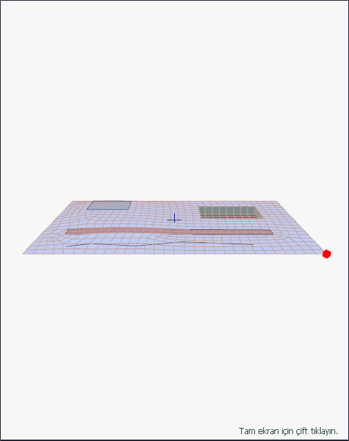
The preview of the created terrain is done on the screen. The settings made in the dialog are simultaneously reflected on the preview screen. The point you are editing is marked as a red point in the preview. |
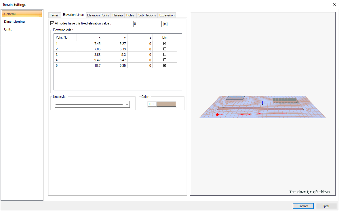
General Tab - Elevation Lines
|
Specifications |
|---|
|
Elevation edit 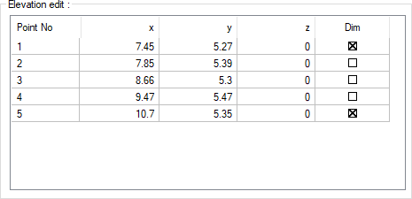
The coordinates of the elevation points placed are given. If wanted, a new value can be entered in the z box. |
|
All nodes have this fixed elevation value The feature is activated and the value entered here is applied to all elevation points. |
|
Line type The line type of the elevation line in the plan is selected. Clicking the down arrow buttons to the right of the boxes opens the list of line types. From this list, the desired line type is selected by clicking with the left mouse button. |
|
Color It is the color of the elevation line in the plan. When the color box is clicked, the appropriate color is selected from the window that opens. |
|
Perspective Preview 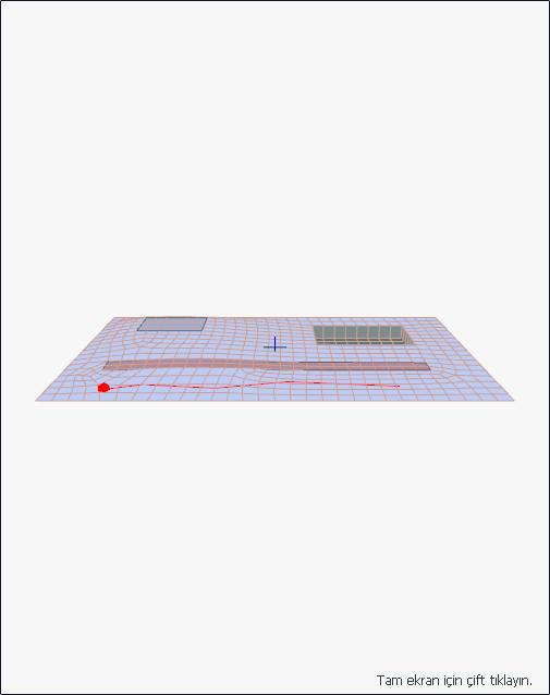
The preview of the created terrain is done on the screen. The settings made in the dialog are simultaneously reflected on the preview screen. The point you are editing is marked as a red point in the preview. |
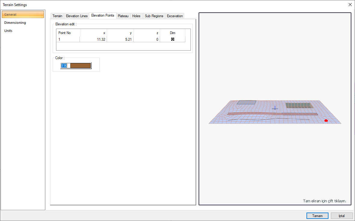
General Tab - Elevation Points
|
Specifications |
|---|
|
Elevation edit 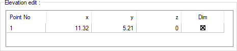
The coordinates of the elevation points placed are given. If desired, a new value can be entered in the z box. |
|
Color It is the drawing color of the line of the elevation points in the plan. When the color box is clicked, the appropriate color is selected from the window that opens. |
|
Perspective preview 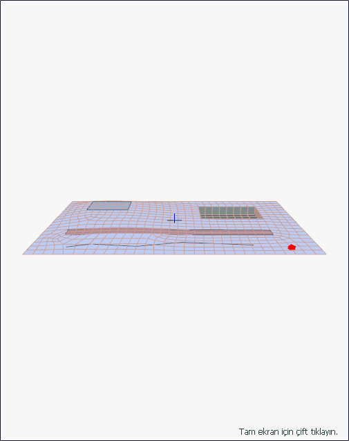
The preview of the created terrain is done on the screen. The settings made in the dialog are simultaneously reflected on the preview screen. The point you are editing is marked as a red point in the preview. |
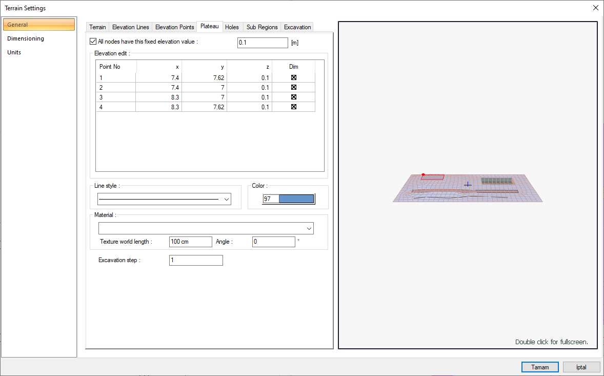
General Tab - Plateau
|
Specifications |
|---|
|
Elevation edit 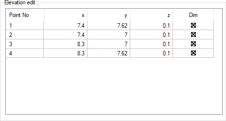
The coordinates of the elevation points placed are given. If wanted, a new value can be entered in the z box. |
|
Line style The line type of the plateau in the plan is selected. Clicking the down arrow buttons to the right of the boxes opens the list of line types. From this list, the desired line type is selected by clicking with the left mouse button. |
|
Color It is the drawing color of the plateau line in the plan. When the color box is clicked, the appropriate color is selected from the window that opens. |
|
Material You can select the material of the plateau surface from the list by clicking. |
|
Texture world length Texture length is entered. For example; If 1 meter is entered, the selected material texture is taken as 1 meter and covered on the selected object. Considering that the texture is in the form of a square, the object surfaces are covered with 1x1 textures arranged side by side. |
|
Angle The angle of the texture is given. With the angle value, you can adjust the angle of the texture according to the direction of its plane. |
|
Excavation step Terrain and pieces of terraşn are given numbers for excavation calculations. The excavations of the terrain and terrain plots with the same number are calculated and shown as total value at once, and the excavation of the terrain or terrain plots that are numbered separately as a separate item. |
|
Perspective Preview 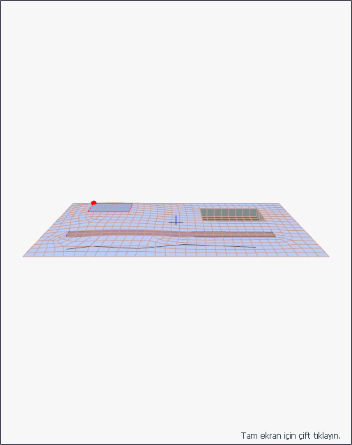
The preview of the created terrain is done on the screen. The settings made in the dialog are simultaneously reflected on the preview screen. The point you are editing is marked as a red point in the preview. |
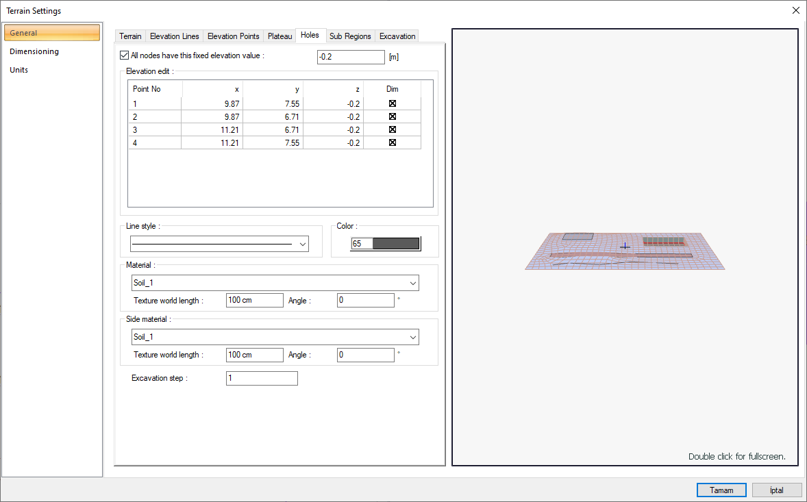
General Tab - Holes
|
Specifications |
|---|
|
Elevation edit 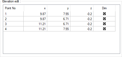
The coordinates of the elevation points placed are given. If wanted, a new value can be entered in the z box. |
|
All nodes have this fixed elevation value
The feature is activated and the value entered here is applied to all elevation points. |
|
Line style The line type of the hole in the plan is selected. Clicking the down arrow buttons to the right of the boxes opens the list of line types. From this list, the desired line type is selected by clicking with the left mouse button. |
|
Color It is the drawing color of the terrain line in the plan. When the color box is clicked, the appropriate color is selected from the window that opens. |
|
Material
You can select the material of the hole top surface from the list by clicking. |
|
Side material
You can select the material of the hole side surfaces by clicking on the list. |
|
Texture world length Texture length is entered. For example; If 1 meter is entered, the selected material texture is taken as 1 meter and covered on the selected object. Considering that the texture is in the form of a square, the object surfaces are covered with 1x1 textures arranged side by side. |
|
Angle The angle of the texture is given. With the angle value, you can adjust the angle of the texture according to the direction of its plane. |
|
Excavation step Terrain and pieces of terraşn are given numbers for excavation calculations. The excavations of the terrain and terrain plots with the same number are calculated and shown as total value at once, and the excavation of the terrain or terrain plots that are numbered separately as a separate item. |
|
Perspective preview 
The preview of the created terrain is done on the screen. The settings made in the dialog are simultaneously reflected on the preview screen. The point you are editing is marked as a red point in the preview. |
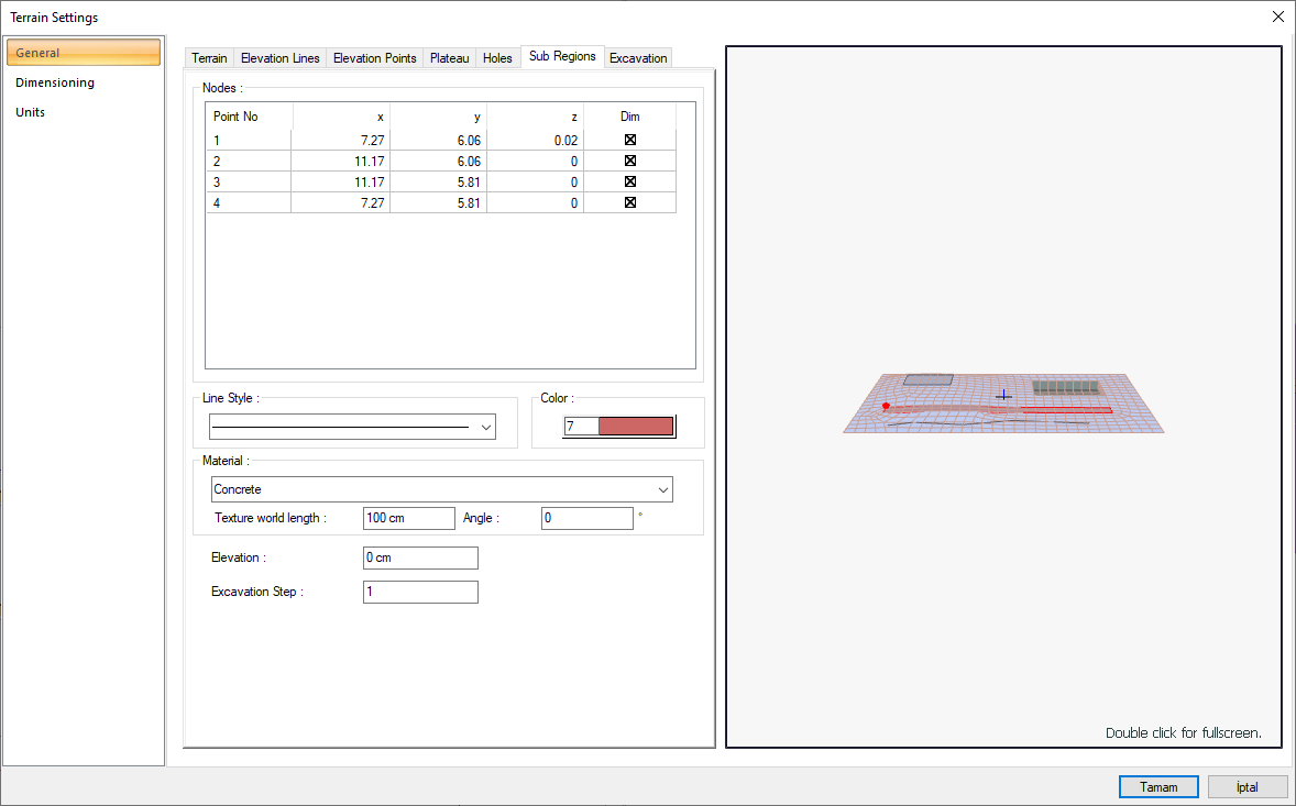
General Tab - Sub Regions
|
Specifications |
|---|
|
Nodes 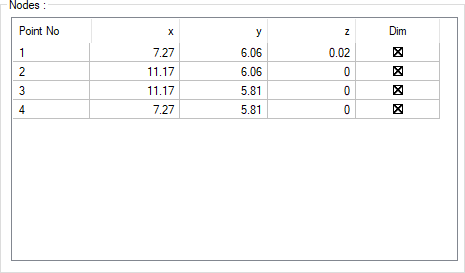
The coordinates of the elevation points placed are given. It cannot be intervened. |
|
Line style The line type in the plan of the sub region is selected. Clicking the down arrow buttons to the right of the boxes opens the list of line types. From this list, the wanted line type is selected by clicking with the left mouse button. |
|
Color The drawing color of the sub region line in the plan. When the color box is clicked, the appropriate color is selected from the window that opens. |
|
Material You can select the material of the sub region from the list by clicking. |
|
Texture world length Texture length is entered. For example; If 1 meter is entered, the selected material texture is taken as 1 meter and covered on the selected object. Considering that the texture is in the form of a square, the object surfaces are covered with 1x1 textures arranged side by side. |
|
Angle The angle of the texture is given. With the angle value, you can adjust the angle of the texture according to the direction of its plane. |
|
Elevation Elevation is given to the lower area. |
|
Excavation step Terrain and pieces of terraşn are given numbers for excavation calculations. The excavations of the terrain and terrain plots with the same number are calculated and shown as total value at once, and the excavation of the terrain or terrain plots that are numbered separately as a separate item. |
|
Perspective Preview
The preview of the created terrain is done on the screen. The settings made in the dialog are simultaneously reflected on the preview screen. The point you are editing is marked as a red point in the preview. |
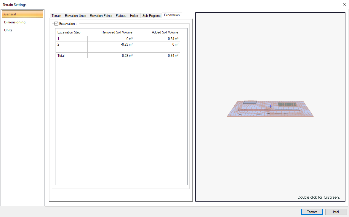
General Tab - Excavation
|
Specifications |
|---|
|
Excavation 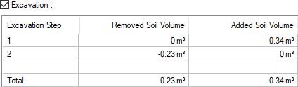
There are calculations according to the numbers given to the terrain and terrain parts. The excavations of the terrain and terrain plots with the same number are calculated and shown as total value at once, and the excavation of the terrain or terrain plots that are numbered separately as a separate item. |
|
Perspective Preview
The preview of the created terrain is done on the screen. The settings made in the dialog are simultaneously reflected on the preview screen. The point you are editing is marked as a red point in the preview. |
Dimensioning Tab
|
Specifications |
|---|
|
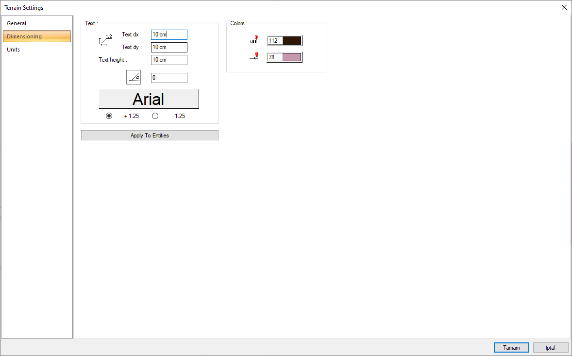
Text dx/dy It is the x/y coordinates that determine the location of the section elevation text on the section line. |
|
Font height It is the writing height of the elevation text. |
|
Angle It is the angle of the elevation writing. |
|
Font Clicking it opens the font dialog. The font of elevations text is selected in the dialog. |
|
Display type Select the display format of the elevation positive value. |
|
Colors 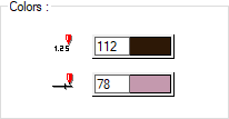
The colors of the elevations text and line are adjusted. In addition, if the box is clicked with the Shift key, the pen thickness of the relevant color can be adjusted. |
|
Apply to entities Dimension settings are applied to terrain and its child entities when the button is clicked. |
Units Tab
|
Specifications |
|---|
|
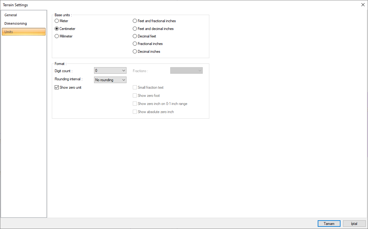
Basic units 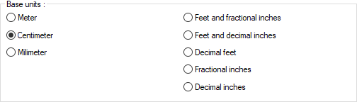
One of the selections is activated by clicking the left mouse button on the job. Meter : If checked, the unit of information text will be meters.
|
|
Digit count 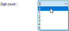
It determines how many digits will be shown after the comma. The desired number is selected from the list. For example, if 2 is selected, units will be shown as two digits after the comma. If 0 is selected, units will not be shown after the comma. |
|
Fractions 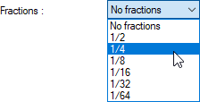
It determines the precision of the dimension to be made in fractional inch format. In the list, there are options with a sensitivity of 1/2, ¼, 1/8, 1/16, 1/32, 1/34. If "no fraction" is selected, units will appear without fractions. |
|
Rounding interval 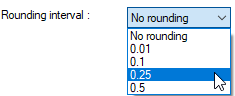
It determines the rounding range of the measurement to be made in meters, centimeters or millimeters. If No rounding is selected, the dimensioning is done at exact value. As the range gets larger, the dimensioning is rounded up to the selected range. |
|
Show zero unit If it is not checked, it does not show the zero and point on the left in dimensioning. For example, it measures 0.20 as 20. If marked, the value 0.20 is scaled as 0.20. |
|
Show zero foot
Determines whether 0 is displayed in the 0-foot gauge (less than 1 foot gauge). For example, if it is not checked, it will show a measure of 0 '- 15 "as -15". If marked, it shows as 0'-15 ". |
|
Show zero inch on 0-1 inch range
For example, a dimension inch with a value of 8'-0 1/6 "is in the range 0-1. If the option is not ticked, the value 8'-0 1/6" will be displayed as 8'-. In other words, inch values in the 0-1 range will not be displayed. |
|
Show absolute zero inch Determines whether to show zero inches in the dimension value where inches is absolute zero. For example, a dimension of exactly 10 'will be displayed as 10'-0 "if this option is selected. If not checked, it will be displayed as 10" -. |
|
Small fraction text When fractional inch format is selected, determines the fractional part to display in upper / lower case. If it is checked, the fraction is slightly above the integer and small, if not, the fraction is shown the same size next to the integer. |