
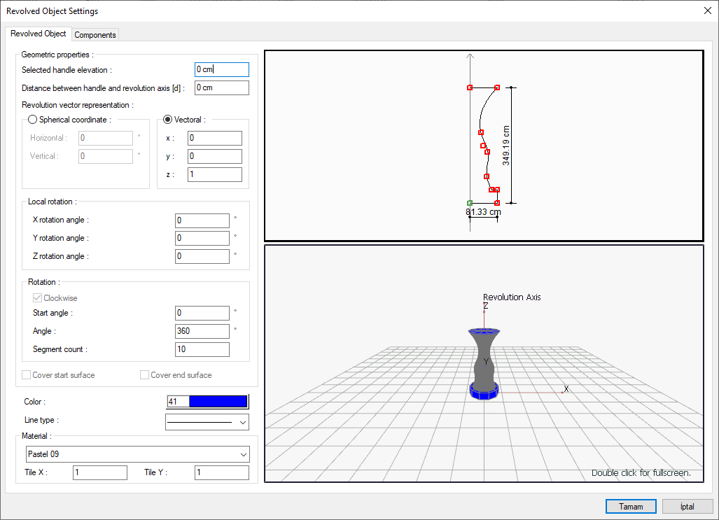
With the Revolved Object Settings command, settings such as elevation, distance between holding and rotation axis, angle, number of parts and material selection are accessed.
Location of Revolved Object Settings Command
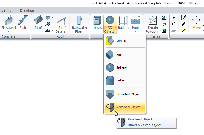
You can access the Settings icon from the 3D Geometric Objects toolbar opened after entering the Revolved Object command under the Entities title of the Ribbon menu Home tab .
Revolved Object Tab
|
Specifications |
|---|
|
Selected handle elevation The level of the object is entered from the story base. |
|
Distance between handle and revolution axis (d) The distance between the axis of rotation used when creating the object and the handle point based on a point of the object is entered. |
|
Spherical coordinate/Horizontal It is the angle that the axle makes with the horizontal (x-axis). |
|
Spherical coordinate/Vertical It is the angle that the axis makes with the vertical (z-axis). |
|
Vectoral X/Y/Z 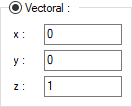
They are the coordinate values expressing the direction of the rotation axis in vector form. |
|
Local rotation X/Y/Z 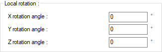
It enables the section to be wrapped around the main axis to be rotated according to its local axis. |
|
Clockwise When this option is checked, it indicates that the rotation will be clockwise, otherwise the rotation will be counterclockwise. |
|
Start angle Determines how much the object will be rotated angularly about the starting point. |
|
Pain Rotation angle is given. The object will be created by rotating the given angle. |
|
Segment count It is the value that determines the number of surfaces of the object to be created by the rotation method. |
|
Cover start surface Closes the star surface of the created object. Otherwise, the start surface of the object will be left open. |
|
Cover end surface Closes the surface of the created object at the end. Otherwise, the end surface of the object will be left open on the remaining side. |
|
Color Choose the color of the object from the color palette that opens when clicked. |
|
Line type The line type of the rotated object line visible in the plan is selected from the list that opens when clicked. |
|
Materiel The material of the object to be used as a coating in the solid model is selected from the list that opens when clicked. |
|
Tile X/Y Determines the number of times to repeat the texture to be wrapped around the object in the X and Y direction. |
|
Schematic drawing 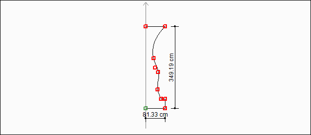
Includes a schematic drawing and dimensions of the revolved object. |
|
3D preview 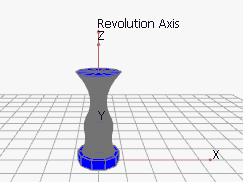
It is a 3-dimensional view of the revolved object. You can rotate the image around itself by holding down the left mouse button and moving it. You can zoom in and out by holding the right mouse button and moving the mouse. |
Components Tab
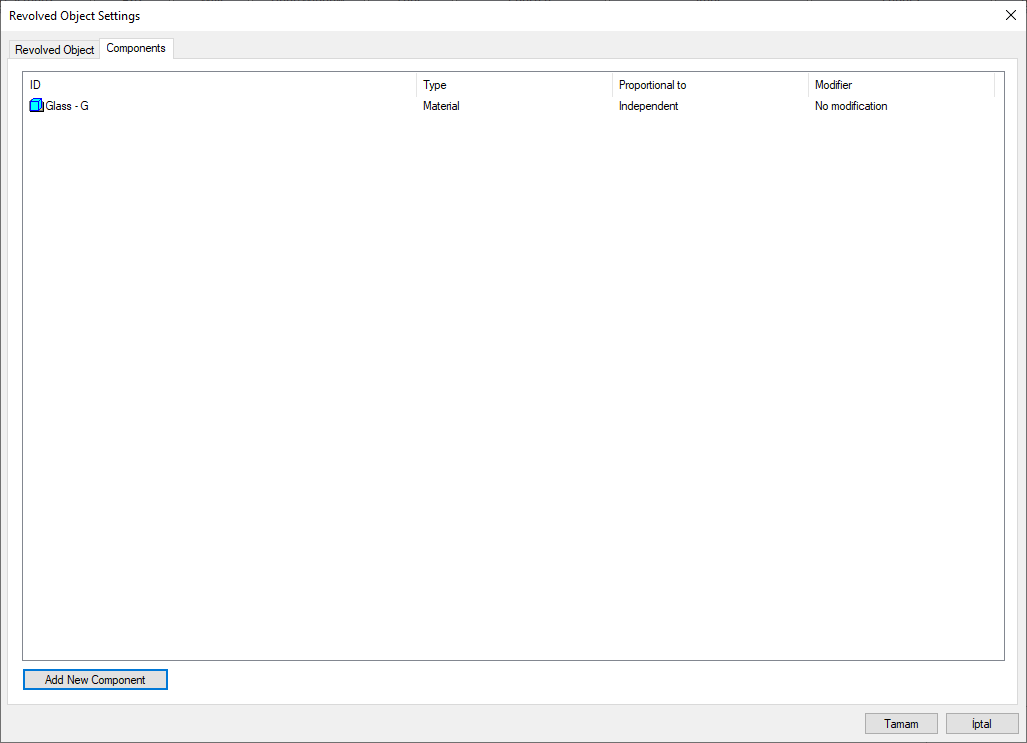
Add building components: Assigns the building materials defined for the detailed building components metering to the wall object.
-
Click the Add Building Component button.
-
The Component Selection dialog will open.
-
In this dialog, click the folder related to the material from the list on the left. Choose the material you want to use.
-
Set the parameters on the right.
-
Click the OK button. The "Component Selection" dialog will be closed. A summary line of the material will appear in the Building Components tab. More than one material assignment can be made to an object.
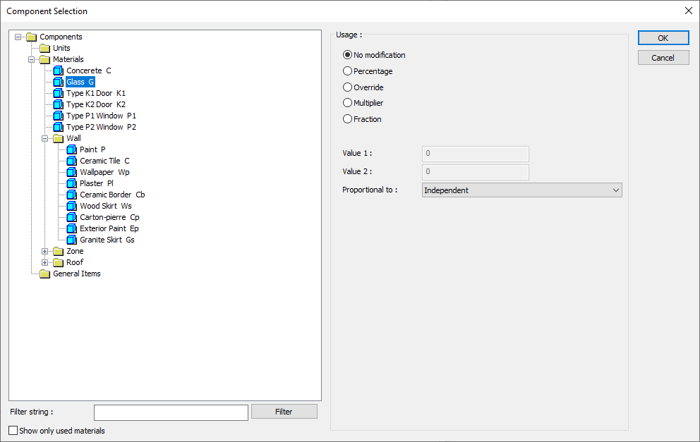
In the usage section
No modification: The amount of material to be assigned for the object in question is marked when it is desired to be used in the size that was previously specified in the material definition.
Percentage: This line is marked when it is desired to be used with the percentage of the amount previously determined in the material definition, as much as the value entered in the "Value 1" line in the same dialog. For example, if the material quantity is 70, if the line “Value 1” says 40, it means the material amount will be used up to 40 * 70%.
Override: This line is marked so that the quantity entered in the “Value 1” line in the same dialog will be used instead of the quantity previously determined in the material definition.
Multiplier: This line is marked in order to use the value found at the end of the multiplication of the value entered in the "Value 1" line in the same dialog with the amount previously determined in the material definition.
Fraction: This line is marked so that the amount determined in the material definition before will be used as the fraction value created by the values entered in the "Value 1" and "Value 2" lines in the same dialog. "Value 1" is the denominator "Value 2" is the denominator.
Proportional to: It is determined to what scale-area, circumference, length etc.-, region-side area, top, edge etc.- the material will be proportioned to. The content of the proportional list box is automatically determined according to the object and the size of the material. For example, a different list will be created if an operation is made for the column, a different list will be created for the library, a different list for the volume, and a different list for the field.
Following are the lines that appear in the proportion list according to the revolved object and material size.
|
Revolved Object |
||
|
Measure |
Listed |
Explanation |
|
Constant |
Independent |
The fixed measure used will be used exactly as the amount. |
|
Area |
Independent |
It means that the area measure found while defining the material will be used exactly as the field value. |
|
Outside area |
It means that the area measure found while defining the material will be used by multiplying the element outer area. |
|
|
Count |
Independent |
The number measure found while defining the material will be used exactly as the number value. |
|
Count |
The number measure found while defining the material will be used exactly as the number value. |
|
Next Topic