
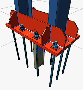
With the Column-Foundation Connection (Stiffened Baseplate) command, column-foundation connection is defined.
Location of the Column-Foundation Connection (Stiffened Baseplate) Command
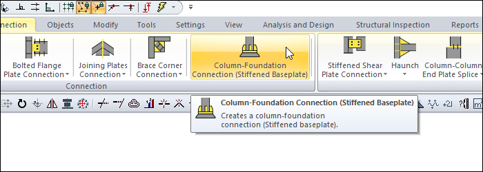
You can access it under the Ribbon menu, Connection tab, Connection title.
Usage Steps
If Draw in Fast Mode is Active
-
From the Connection menu, click on theColumn-Foundation Connection (Stiffened Baseplate) icon.
-
In 3D perspective view, move the mouse pointer closer to the element, close to the support
-
After this process, the virtual image of the connection will appear.
-
If the connection is suitable, create the connection by clicking the left mouse button.
-
The connection will occur with default settings.
If Draw in Fast Mode is Inactive
-
From the Connection menu, click on the Column-Foundation Connection (Stiffened Baseplate) icon.
-
Click the column then the beam before the 3D perspective view.
-
The column-foundation connection (stiffened baseplate) settings dialog will open.
-
The connection will occur when the wanted settings are made and the OK button is clicked.
Location of the Column-Foundation Connection (Stiffened Baseplate) Settings Dialog
If the draw in fast mode is active, the connection settings will be opened automatically.
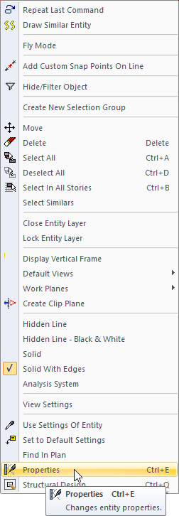
If the draw in fast mode is inactive, select the connection and click the right mouse button. Click the Properties line from the right click menu that opens.
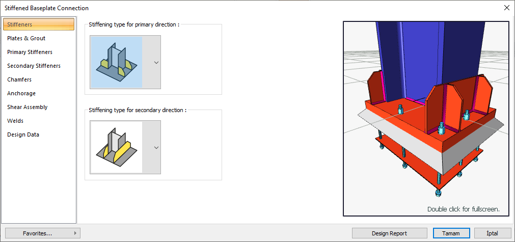
Column-Foundation Connection (Stiffened Baseplate) Settings Dialog
Stiffeners Tab
|
Specifications |
|---|
|
Stiffening type for primary direction 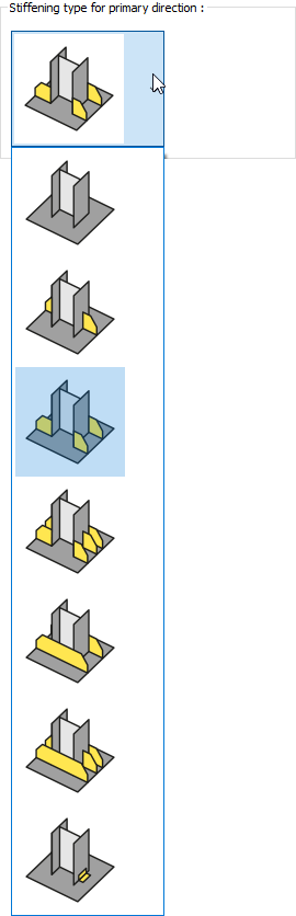
Stiffening type in the primary direction is selected from the options. |
|
Stiffening type for secondary direction 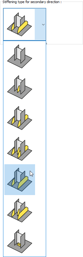
Stiffening type in the secondary direction is selected from the options. |
|
Preview 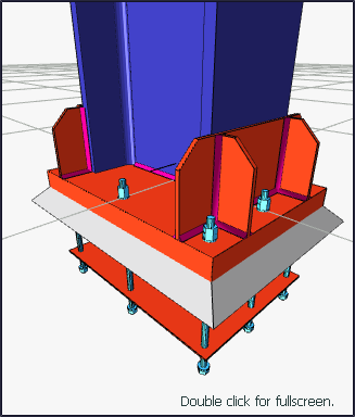
There is a preview of the connection. The selection made and the entered values can be followed simultaneously in the preview. |
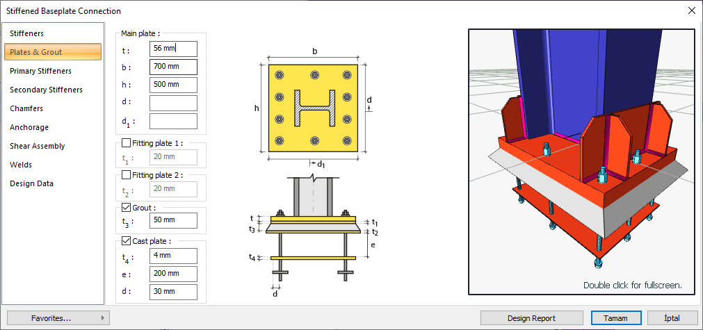
Plates and Grout Tab
|
Specifications |
|---|
|
Main plate 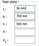
The dimensions of the main plate are determined by entering values. The values to be entered are shown in the schematic drawing. |
|
Fitting plate 1 Fitting plate 1 dimensions are determined by entering values. The values to be entered are shown in the schematic drawing. |
|
Fitting plate 2 Fitting plate 2 dimensions are determined by entering the values. The values to be entered are shown in the schematic drawing. |
|
Grout It is determined by entering values for grout. The values to be entered are shown in the schematic drawing. |
|
Cast plate 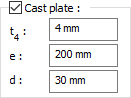
Cast plate dimensions are determined by entering values. The values to be entered are shown in the schematic drawing. |
|
Schematic drawing 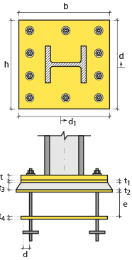
Connection and plate values are shown on the schematic drawing. |
|
Preview
There is a preview of the connection. The selection made and the entered values can be followed simultaneously in the preview. |
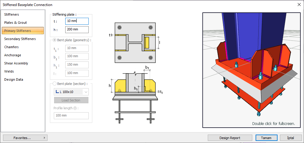
Primary Stiffeners Tab
|
Specifications |
|---|
|
Stiffening plate 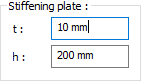
Stiffening plate dimensions are determined by entering values. The values to be entered are shown in the schematic drawing. |
|
Bent plate (geometry) 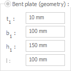
The bent plate geometry is determined by entering values. The values to be entered are shown in the schematic drawing. |
|
Bent plate (section) 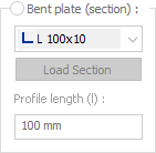
The bent plate section is determined by entering values. The values to be entered are shown in the schematic drawing. |
|
Schematic drawing 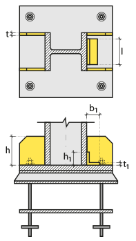
Connection and plate values are shown on the schematic drawing. |
|
Preview
There is a preview of the connection. The selection made and the entered values can be followed simultaneously in the preview. |
Secondary Stiffeners Tab

|
Specifications |
|---|
|
Edge and center plates 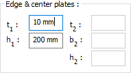
Edge and center plate dimensions are determined by entering values. The values to be entered are shown in the schematic drawing. |
|
Bent plate (geometry) 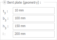
The bent plate geometry is determined by entering values. The values to be entered are shown in the schematic drawing. |
|
Bent plate (section) 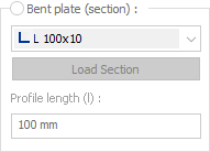
The bent plate cross section is determined by entering values. The values to be entered are shown in the schematic drawing. |
|
Schematic drawing 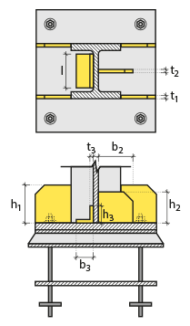
Connection and plate values are shown on the schematic drawing. |
|
Preview
There is a preview of the connection. The selection made and the entered values can be followed simultaneously in the preview. |
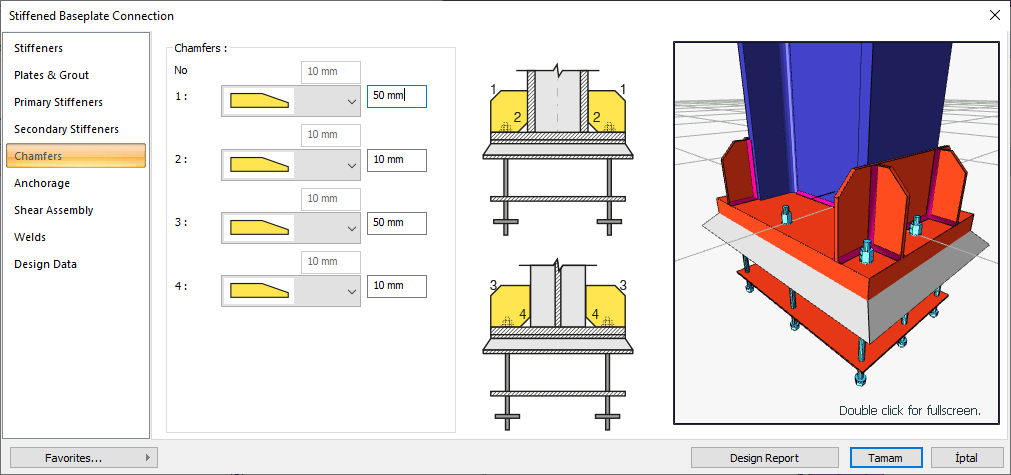
Chamfers Tab
|
Specifications |
|---|
|
Chamfers 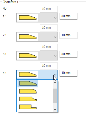
For easy assembly of the plates in the field, the use of slope, slope type and geometric properties are determined by entering the value. |
|
Schematic drawing 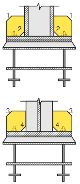
Connection, notching and cutting values are shown on the schematic drawing. |
|
Preview
There is a preview of the connection. The selection made and the entered values can be followed simultaneously in the preview. |
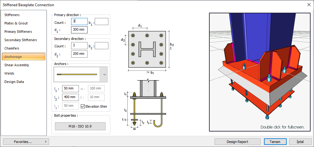
Anchorage Tab
|
Specifications |
|---|
|
Primary direction 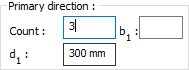
It is determined by entering the number of anchors in the primary direction and the distance values. The values to be entered are shown in the schematic drawing. |
|
Secondary direction 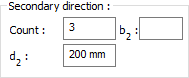
It is determined by entering the number of anchors in the secondary direction and the distance values. The values to be entered are shown in the schematic drawing. |
|
Anchors 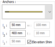
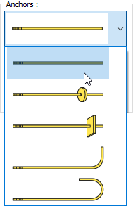
Anchor type is selected from the list. Anchor dimensions are determined by entering values. The values to be entered are shown in the schematic drawing. |
|
Bolt properties 
The Hole and Bolt Parameters dialog is opened by clicking on the bolt properties button. The bolt properties are set in this dialog. |
|
Schematic drawing 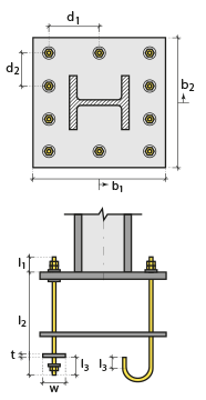
Connection and plate values are shown on the schematic drawing. |
|
Preview
There is a preview of the connection. The selection made and the entered values can be followed simultaneously in the preview. |
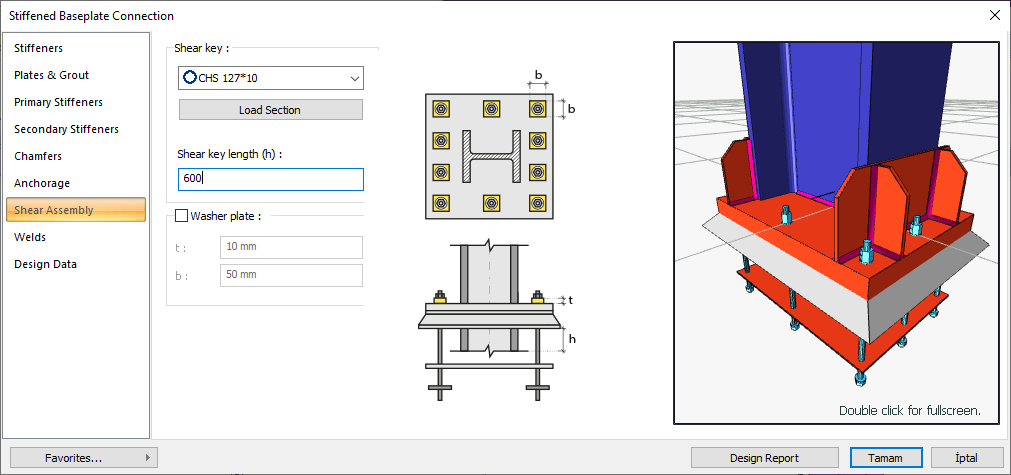
Shear Assembly Tab
|
Specifications |
|---|
|
Shear key 
One of the ready-made profiles is selected from the list as a shear key. By clicking on the load section button, you can reach the ready section library and reach the list of American and European finished rolling sections and select from the list. |
|
Shear key length The shear key length is entered. The values to be entered are shown in the schematic drawing. |
|
Washer plate 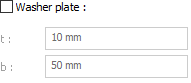
The washer plate dimensions are determined by entering the values. The values to be entered are shown in the schematic drawing. |
|
Schematic drawing 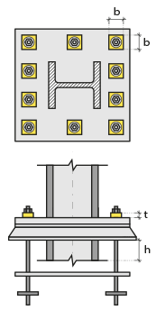
Connection and plate values are shown on the schematic drawing. |
|
Preview
There is a preview of the connection. The selection made and the entered values can be followed simultaneously in the preview. |
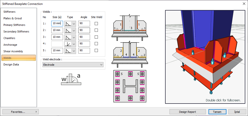
Welds Tab
|
Specifications |
|---|
|
Welds 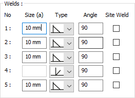
The thickness, type and angle values of the welds to be made at the connections are given. The information on whether it will be done on the construction site or not is entered. |
|
Weld electrode The strengths of the welding electrodes are defined in the design inputs. The strength of the main element in the weld joint is controlled under the condition that it has less strength than the weld strength. If necessary, click the list and define "Create New…". To create the welding electrode, give the information "Name" and "Weld metal tensile strength" in the dialog that opens after clicking "Create New". Welding geometry is determined automatically by the program. These properties can be changed to easily determine the connection properties. Geometry features are in accordance with industry standards and in the form specified in AISC. |
|
Schematic drawing 
Connection and weld values are shown on the schematic drawing. |
|
Preview
There is a preview of the connection. The selection made and the entered values can be followed simultaneously in the preview. |
Design Data Tab
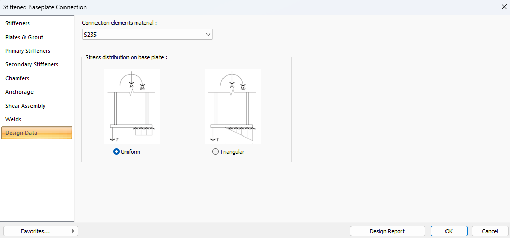
In the Design Data tab, you can define the plate material and select the stress distribution type for the base plate, which determines the method used in the connection design.
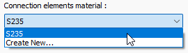
If necessary, click the list and define "Create New…". To create the connection elements material, give the information material definitions and values in the dialog that opens after clicking "Create New".
You can choose between the uniform and triangular methods as the stress distribution approach for the base plate. To make a selection, click once on the checkbox next to the method you want to use. If the box is filled in blue, it means the option is selected.
Next Topic