
-
Conditions for the placement and clamping of longitudinal reinforcement are automatically applied.
-
Lap joint is applied automatically in the middle of the opening only in mounting reinforcements.
-
It is applied automatically in accordance with the clamping length 7.4.3.1 .
ICONS
DTS = Earthquake Design Class
f ctd = Design tensile strength of concrete
f yd = Design yield strength of longitudinal reinforcement
l b = Interlock length given for tensile reinforcement at TS 500
ρ = ratio of upper or lower tensile reinforcement in beam support
ϕ = Reinforcement diameter
TBDY Figure 7.7 specifies the conditions for longitudinal reinforcement placement and clamping.
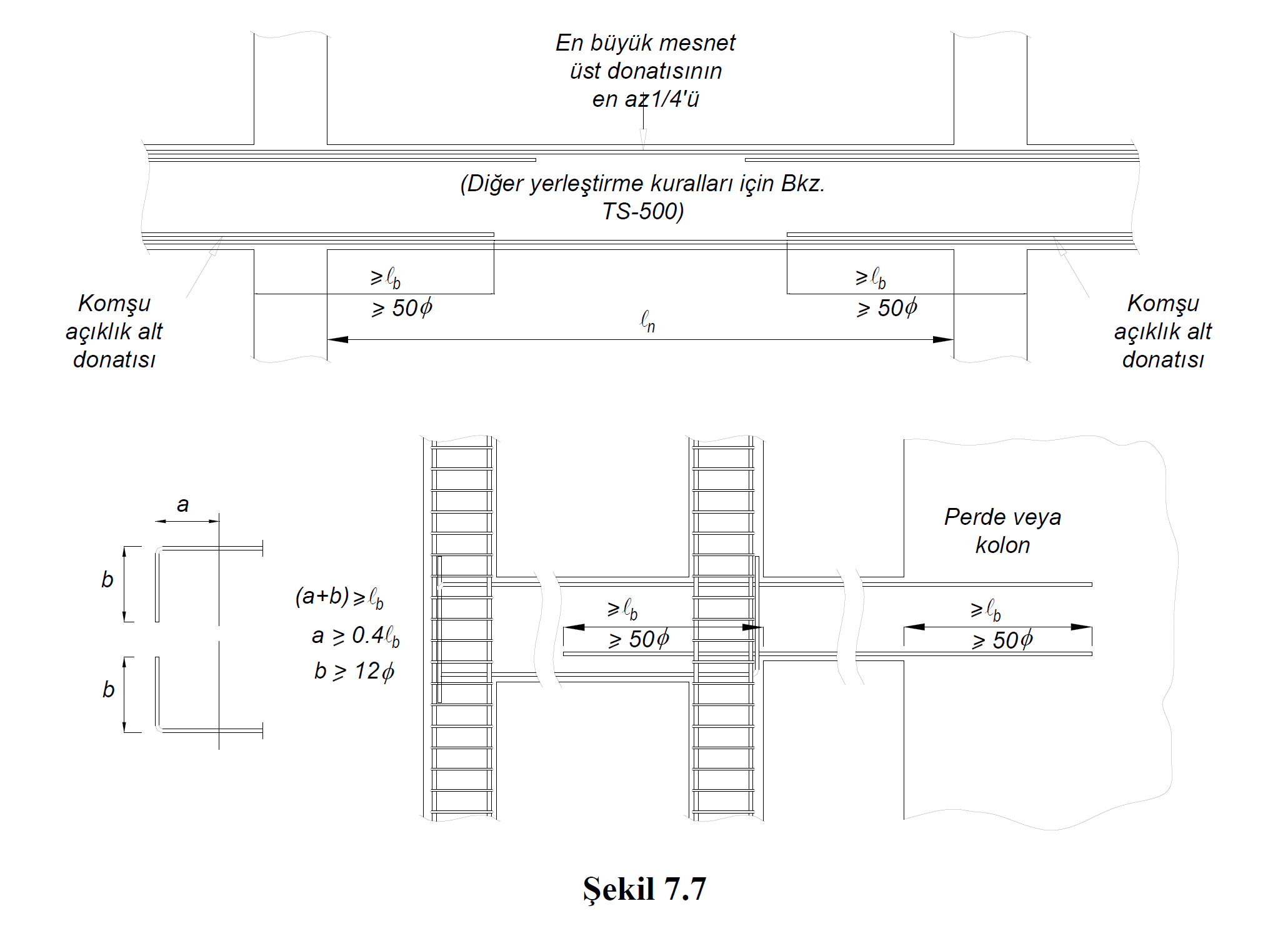
Conditions for the arrangement of web reinforcement are given in 7.4.3.1 (a) , (b) and (c) of TBDY .
(a) At least 1/4 of the larger of the support top reinforcements at both ends of the beam will be continued continuously along the whole beam. The remaining part of the support upper reinforcement shall be arranged in accordance with TS 500 so that no unmet moment is left along the beam.
(b) In cases where the beams joining the column do not continue on the other side of the column, the upper and lower reinforcement of the beams shall be extended to the opposite surface of the core of the column wrapped with stirrups and bent 90 degrees from the inside of the stirrups. In this case the total length of the horizontal part of the remaining 90 degree bent vertical part of longitudinal reinforcement inside the column specified in TS 500 straight development length l b 'will be less than. The horizontal part of the 90 degree hook shall not be less than 0.4l b and the vertical part shall not be less than 12ϕ. Straight development length dimension of the curtain and α l b from 50φ and from the columns in excess, the engagement of the longitudinal reinforcement may be provided as flat without 90 degree hook.
(c) In case of joining of beams to columns from both sides, beam bottom reinforcements shall be extended from the face of the column adjacent to the span, by not less than 50ϕ, at least by the clamping length given in TS 500 by 1 b . In cases where this possibility is not available for reasons such as height difference in beams, clamping shall be done as described in paragraph (b) above for cases where the beam does not continue on the other side of the column.
The use of sleeved and overlapped welding joints specified in Article 7.4.3.2 (b) of TBDY is not allowed.
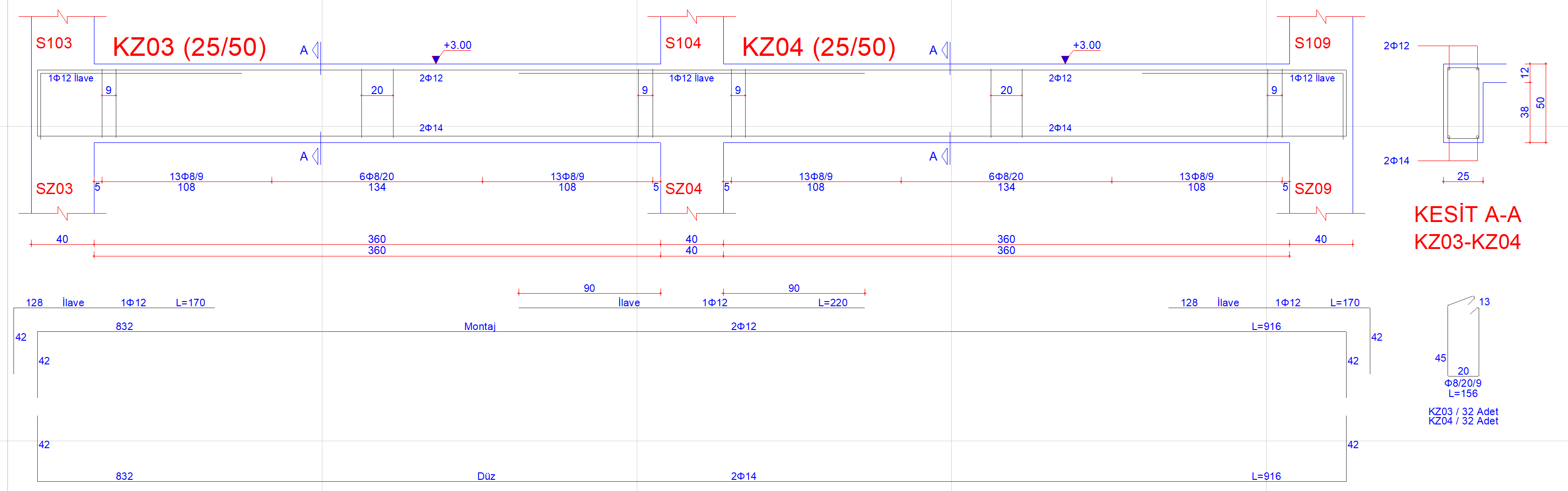
Longitudinal reinforcement conditions and application of clamping length l b can be examined in the Reinforced Concrete Configuration section from the Beam Reinforced Concrete window . In the picture below, an example of Reinforced Concrete Configuration is given.
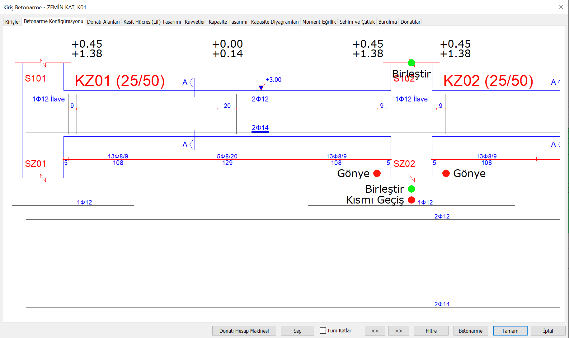
Beam expansions are shown in accordance with clamping length l b and TBDY Article 7.4.3.1 .
Next Topic