
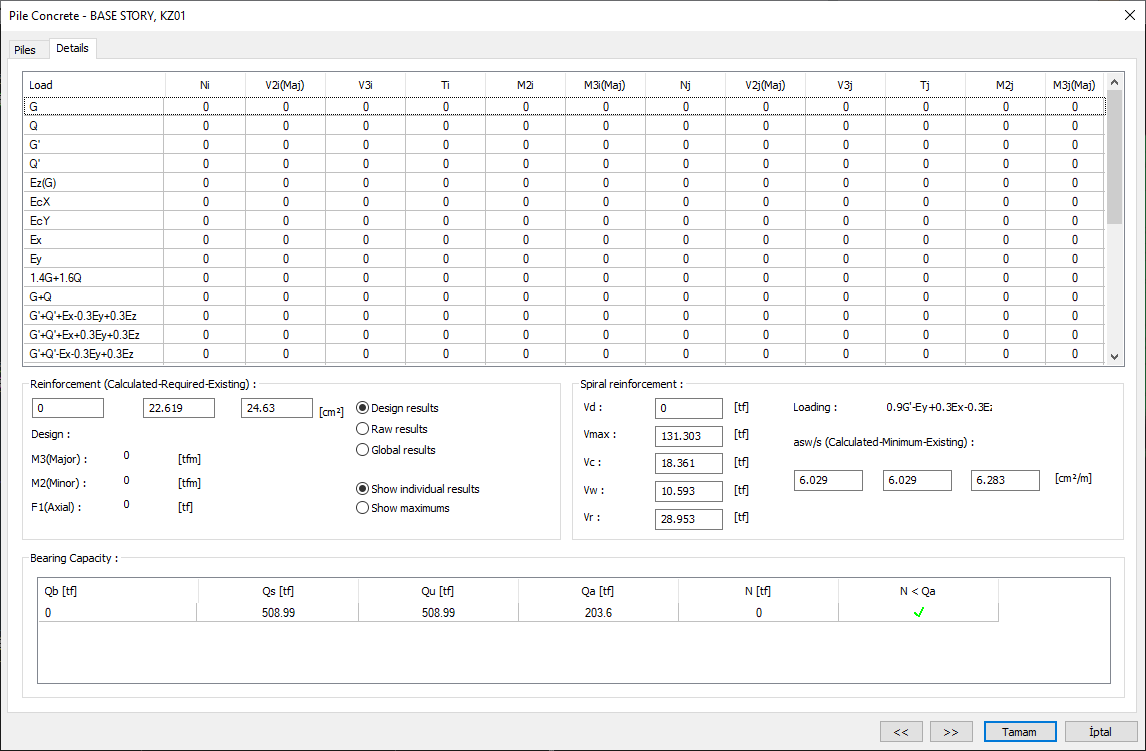
The pile reinforcement concrete design results and the inadequacy of the pile are displayed in the Pile Concrete dialog. In the Pile Concrete dialog, the results of the transverse and longitudinal reinforcement and the design internal force results are given.
Location of Pile Concrete Dialog
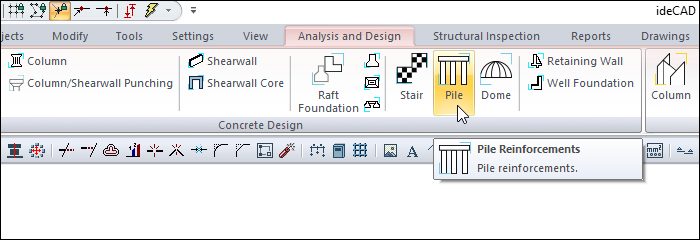
After analysis, you can access it by clicking on the Pile command under the Concrete Design title of the ribbon menu Analysis and Design tab .
General Specifications of Pile Concrete Dialogue
|
Summary Information The summary information about the line where the cursor is located is given in the name of the dialog in story, pose format. 
For example BASE STORY, KZ01 |
|
Using the Shift key In this tab, you can select more than one row with the Shift key, enter a value by double-clicking any cell whose value is open to change, and you can make that value apply to all selected rows. |
|
Using the Ctrl key Ctrl key, on the other hand, selects the lines in between one by one. |
|
Previous The cursor moves to the previous line. |
|
Next The cursor goes to the next line. |
|
OK It saves the changes made and closes the dialog. |
|
Cancel Closes the dialog without saving the changes made. |
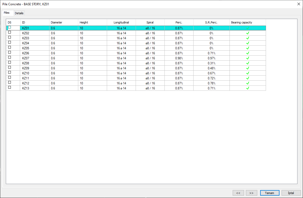
Piles Tab
|
Specifications |
|---|
|
DS It is the reinforcement fixing column. If marked, the reinforcement is fixed. |
|
ID 
Pile is the name of the foundation in the plan. (KZ1, KZ2, KZ12 etc.) In case of negativity, a term related to negativity is added next to the name. Like KZ11 (M) .. |
|
Diameter 
Pile is the diameter of the foundation. |
|
Height 
Pile is the height of the foundation. |
|
Longitudinal 
It is the value of the rebars placed in the length of the pile foundation in terms of diameter and number. |
|
Spiral 
Pile is the value of the rebars placed on the foundation as a spiral in terms of diameter and number. |
|
Perc. 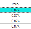
It is the percentage ratio of the total longitudinal rebar amount to the pile foundation area. (Perc. = 100 * TotalAs / PileArea) |
|
S.R.Perc. 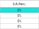
It is the percentage ratio of the amount of rebar calculated from the design effects to the pile foundation area. SRPercentage = 100 * AccountAs / PileArea |
Details Tab
|
Specifications |
|---|
|
Table of forces 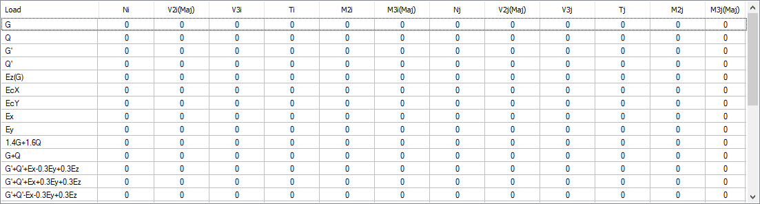
Load: The name of the respective load or load combinations.
|
|
Design results After the analysis, the regulation conditions have been applied, therefore it shows the end forces that have undergone changes and going to the design. In addition, the values used are shown in bold. End forces are values calculated on the element local axes. |
|
Raw results After analysis, it shows the raw end forces that are not applied to the regulation conditions. End forces are effects on the element local axes. |
|
Global results After the analysis, these are the values in global coordinates of the extreme forces that are not applied regulation conditions. |
|
Show individual results For 4 modal analysis cases, 4 different results are obtained from each earthquake loaded combination. If you want the program to display the values obtained for each modal state one by one, you should check this option. |
|
Show maximums The biggest values of 4 different results obtained from each load combination for 4 different modal cases are shown in the table. |
|
Reinforcement (calculated-required-existing) 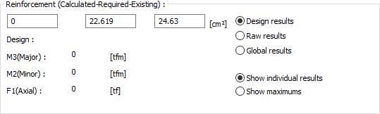
Design: It is the name of the combination used in pile foundation reinforcement calculation.
|
|
Vd Vd: It is the shear force calculated under the combined effect of vertical loads and earthquake multiplied by the load factors. |
|
Vmax It is the maximum shear force that the section can carry.
|
|
Vc It is the shear force carried by concrete.
|
|
Vw It is the contribution of shear rebar to shear strength.
|
|
Vr It is the maximum cutting force value that the section can carry. The design shear force Ve used in stirrup calculation is not allowed to exceed Vr.
|
|
Loading And the loading that gives its value is the name of the combination. |
|
asw/s (calculated - minimum-existing) 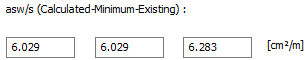
It is the area of 1 meter of single arm stirrup found for densification zone as a result of shear force calculation. And it is calculated.
|
Next Topic
Related Topics