
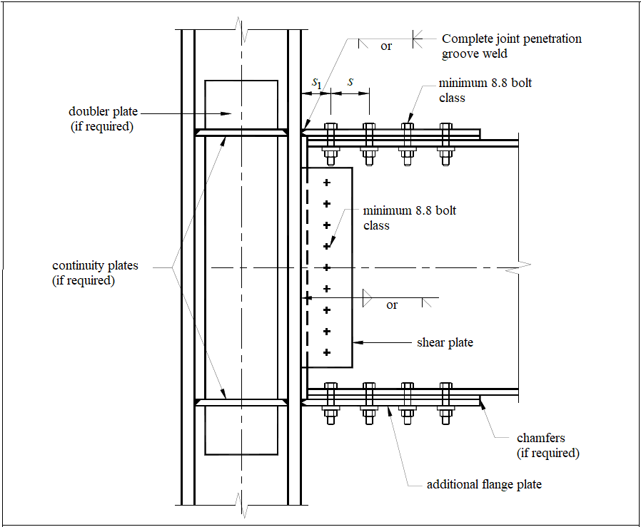
Bolted flange plate moment connections are formed by a weld to the column flange and bolted to the beam flange. The connection model is made automatically in accordance with TBDY 2018 Figure 9B.4.
The Requirements to be Fulfilled
-
It must be capable of providing the relative storey drift angle of at least 0.02 radians for limited ductility level and at least 0.04 radians for high ductility level as specified in Annex 9B,
-
For hot-rolled wide flange sections, the details below should be followed.
General Principles
-
Only YDKT method will be used in the dimensioning of members. The strength coefficients used for limit situations are:
-
Ductile failure limit state (Yielding Limit State):
-
Brittle failure limit state (Rupture Limit State):
-
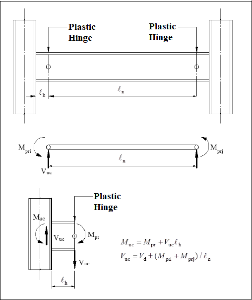
Plastic hinge length lh is defined in the application rules section for each connection type.
-
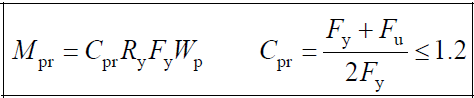
Plastic hinge moment values:
-
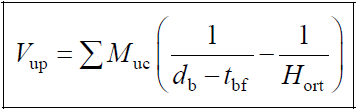
The Vuc used in the dimensioning of the connection is determined according to the equation in the figure above by summing the shear force determined on the basis of the yielding limit state with the shear force calculated from the combination of 1.2G + 0.5Q + 0.2S on the plastic hinge at the end of the beam.
-
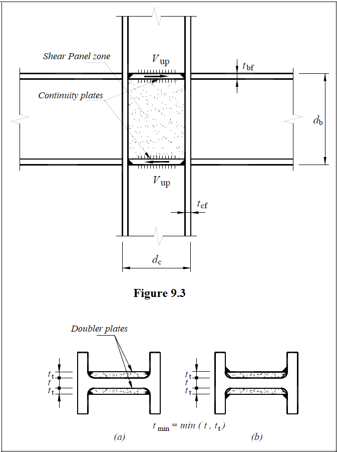
The shear strength required for the panel zone is calculated by using the column shear force generated by the possible plastic moments of the beams connecting to the column.
Prequalification Limits

Next Topic