
ICONS
g = Gravitational acceleration [m / s 2 ]
m j (S) = Singular mass acting on typical finite element node j [t]
n = Live load contribution coefficient
w j (S) = Typical finite element node j singular weight acting [kN]
w G, j (S) = singular constant weight acting on typical finite element node j [kN]
w Q, j (S) = typical finite element node j acting singular additional (under live load) weight [kN]
TBDY Article 5.4.6. Modeling of Masses
Modeling of the masses will be done according to 4.5.9 .
TBDY Section 4.5.9. Modeling of Masses
4.5.9.1 - In case the structural system elements are modeled as rod, plate (membrane) or shell finite element, the individual node masses are assigned as components of distributed masses in the coverage areas of connected finite elements. Singular masses at finite element nodes are defined to correspond to only two horizontal or additional vertical translation degrees of freedom.
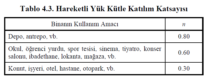
4.5.9.2 - The singular mass m j (S) acting on the typical finite element joint j will be calculated by Equation (4.16) .

Here w j (S) and w j (S) denote the resultant constant load and live load acting on the finite element node j. Eq. (4.16) , located in the movable load mass participation coefficient , n, Table 4.3 'are given. In industrial buildings, n = 1 will be taken for fixed equipment weights, but crane lifting loads will not be taken into account in the floor weights. 30% of snow loads will be taken into account in calculating the weight of the roof floor. The condition given in 6.1.3 regarding non-structural elements and fittings shall be taken into account.
4.5.9.3 - In case floor slabs are modeled as rigid diaphragms in their own planes according to 4.5.6.4 , the storey masses are defined in such a way that they correspond to three independent rigid movement degrees in plane at the main node in the center of mass. Independent degrees of freedom are usually chosen as two horizontal translational degrees of freedom and rotational degrees of freedom around the vertical axis passing through the main node. Equation (4.16) shall be taken as basis in the calculation of the floor masses . Masses corresponding to the vertical degrees of freedom in the slab shall be defined as in 4.5.9.2 .
Next Topic
Related Topics