
Data inputs to the ideCAD are made on an object basis. In this context, every drawing drawn on the drawing screen is called an object. These objects are smart objects. Smart objects are dependent on nodes and all objects have nodes. Elements such as walls and beams are taken into account in inner dimensioning. When changes are made to the wall or beam, the change is reflected in the inner dimensioning simultaneously. Thanks to the object dependency, the changes you make are automatically reflected on the other objects to which it is dependent.
Smart Objects
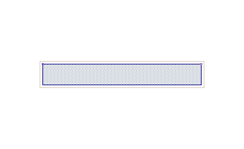
The created smart objects contain many features. For example, a wall to be drawn in the drawing area is not an object consisting of only two wall lines, two plaster lines and a wall hatch. This wall has thickness, height, even unit weight. Its three-dimensional view can be sectioned by cutting it from the desired location.
|
Wall plan |
|
|
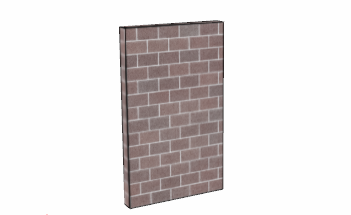
3D view of the wall |
|---|
|
|
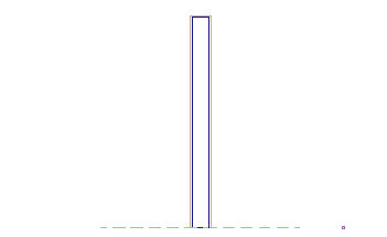
Wall section |
|
Objects and Node Points
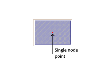
Objects have nodal logic. Nodal points are the coordinates where the geometric information of the objects is stored. Objects are dependent on nodes. All objects in the program have one or more nodes, depending on the type of objects.
Below are examples of objects with one or more nodes.
|
Column - single node |
|
|
Beam - two nodes |
|---|
|
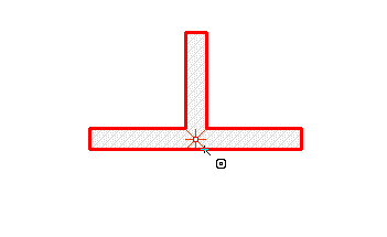
Moving a Node
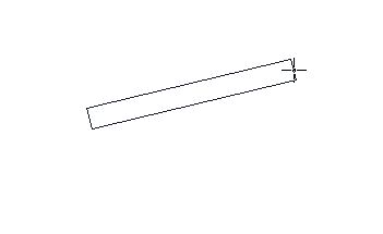
In single-node objects (such as a column), the object is moved when the node is moved, since the entire object is attached to this node. In objects with two or more joints (beam, wall, line, arc, roof surface, etc.), the shape of the objects changes when a single node is moved. To move all such objects, all nodes must be moved together.
Below are examples of joint move operations.
|
Move a column node |
|
Step 1: Selecting the node |
|
|
Step 2 : Moving the node |
|
|
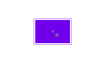
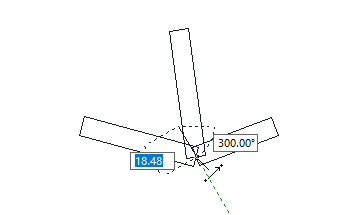
Move a beam node |
|---|
|
Step 1: Selecting the node |

|
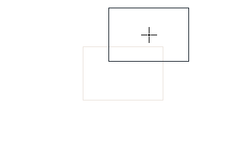
|
Step 2 : Moving the node |
|
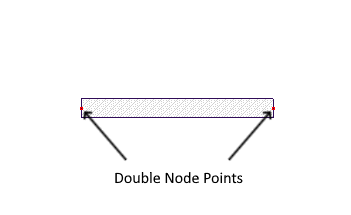
When two or more nodes are overlapped, it becomes a single node. As a result, objects connected to these nodes also become dependent on each other. When the node is moved, the objects attached to it are also moved or moved.
|
Selecting a node |
|
|
Moving a node |
|---|
|
Object Dependence
Thanks to object dependency, if changes made in an object affect other objects, these effects are automatically reflected to other objects by the program. You do not need to do additional processing. Below are examples of this situation.
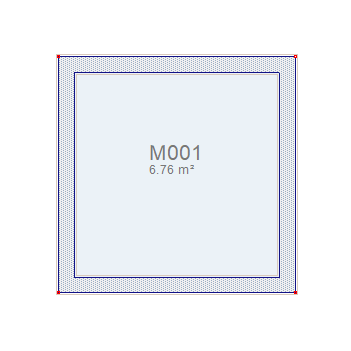
Site object and area calculation:
-
Create a square polygon with walls. Let the lengths of the walls be 3 metres and the thickness of 20 cm.
-
Create a space for a confined space. Closed area will be calculated in square meters and written in the site.
-
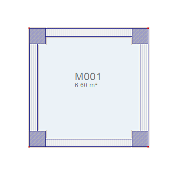
Place corner pillars of 40x40 cm on the wall corners. Let the columns align to outside corners
-
After placing the columns, the square meter of the site will also change.
|
Zone area before defining column (6.76 m2) |
|
|
Zone area after defining column (6.60 m2) |
|---|
|
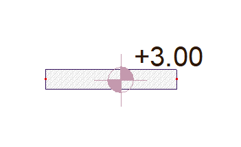
Elevations with Level Dimension command:
-
Draw a beam and click the level dimension icon.
-
Move the mouse cursor over one of the beams and click the left mouse button.
-
Beam elevation will be written on the beam.
-
Click and select the same beam with the left mouse button and enter its properties.
-
From the beam settings dialog, change the beam elevation value to -50 (cm).
-
When you click the OK button and close the dialog, the level value will change.
|
Beam level 0 |
|
|
Beam elevation -50 (cm) |
|---|

|
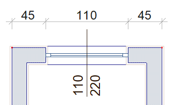
Outer Dimension:
-
Click the Outside Dimension icon.
-
Click on your wall with the left mouse button and right click to finish the selection process.
-
Click any point on the outside of the wall with the left mouse button. Outer dimensioning will occur.
-
Enter the settings of your window defined on the wall.
-
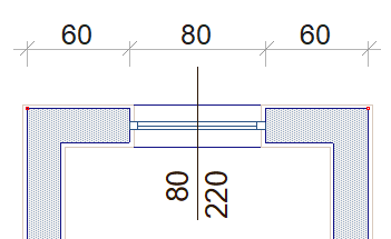
Change the window width, saying OK, close the dialog.
-
Your outside size will change.
|
Window width 110 cm |
|
|
Window width 80 cm |
|---|
|
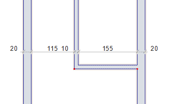
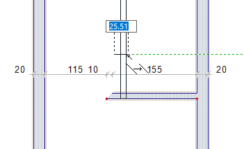
Inner Dimension:
-
Click the Inner Dimension icon.
-
Draw the line that you want your inner dimensioning to go through so as to cut your walls.
-
When you complete the line drawing, your inner dimensioning will be formed.
-
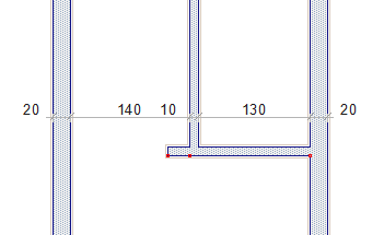
Move your wall 25 cm to the right.
-
When you complete the migration process, your inner dimensioning will change.
|
First position |
|
|
Moving the wall |
|---|
|
|
Final position |
|
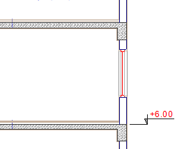
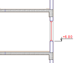
Section Elevation:
-
Click the Section Elevation icon.,
-
Click on your tile in your section drawing. Your elevation will be created automatically.
-
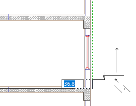
Select the level you have created and move it to the window level.
-
When moving completed, elevation value will change.
|
First position |
|
|
Moving section elevation |
|---|
|
|
Final position |
|
Next Topic