
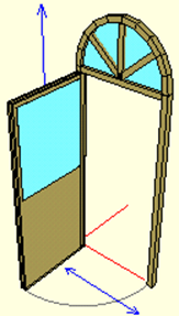
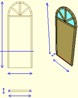
The door in the image below is created by following the steps. In this title, the construction of the door seen below will be explained step by step.
Planning on Paper
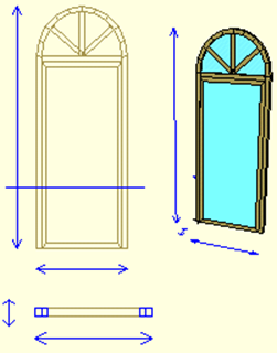
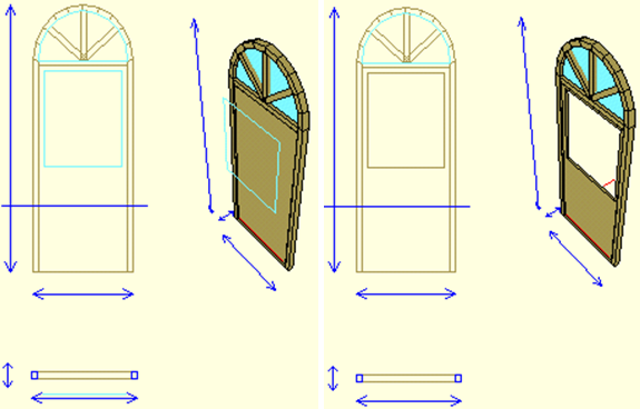
Before making a window or door, it would be helpful to plan it on paper. In this way, while the sizing process becomes easier, the possibility of making mistakes will be reduced.
Dio Design Settings
In this step, we will determine our working area before starting the design. This process will allow us to check the size of your window or door during design.
Adjusting the Height of Dio Design
-
Click the Settings / Design DIO Adjust Height line.
-
As soon as you click, your dio design height on the z axis will move with your mouse movement (Height 2.35 meters for this design.)
-
If you want , you can adjust the height by pressing the Z key and entering a value. When you press the Enter key after entering the value, the design height will be adjusted.
-
If you like the design height of the mouse while moving the lower right corner, depending on the height (Z) control you can adjust by clicking CAE reaches the desired height.
Adjusting the Dio Design Width
-
Click the Settings / Design DIO Set Width row.
-
As soon as you click, your dio design width on the x axis will move with your mouse movement (Width is 0.90 meters for this design.).
-
If you want , you can adjust the width by pressing the X key and entering a value. When you press the Enter key after entering the value, the design width will be adjusted.
-
If you like the design width of the mouse, depending on the value of the width of the lower right corner moves (X) can be set by clicking reaches the desired width checking.
Determining Cash Outlines
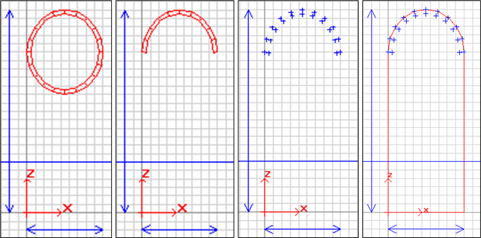
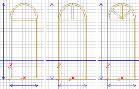
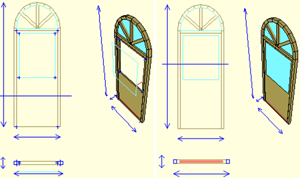
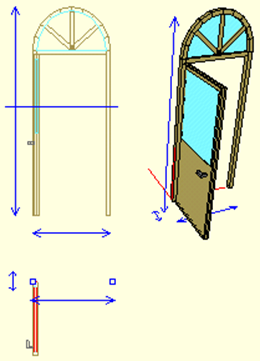
You can determine the outline of the box by referencing the nodes of the auxiliary objects drawn. The upper arch can be thought of as a semicircle and drawn with a circle case. Since half of the circle case will be used, its dimensions should be considered as x = 90, y = 100 cm. Thus, arch dimensions will be x = 90, y = 50 cm.
-
Click on the Line Drawing / Circle Frame-Wing .
-
Draw a circle case 90 cm wide and 100 cm tall.
-
Move this circle so that its right edge is at x = 0 and its top edge is at y = 240. (Press the right button on the safe. Select the move command from the pop-up menu. Click on the case with the left button. The safe will start to move depending on the mouse. After it comes to the appropriate place, click with the left button to place the safe.)
-
Click the Change / Keep Case-Wing Edges row.
-
Hide all the edges of the lower half of the circle case by clicking on them one by one.
-
Click the Jump to Support / Object Points row.
-
Select the circle box (The jump points of the circle box have been activated.).
-
Wipe Circle Vault.
As the next step, you can create the casing outline.
-
Click the Line Drawing / Polygon .
-
Begin the polygon by clicking your first point at X = 0, Y = 0. Click the first outer right jump point of the circle vault as the second point and move around the circle by clicking the outer jump points. Finally, click on the lower left corner node at the point X = 0, Y = 0. Click the Finish button to end the polygon.
-
Click on the Support / Delete Free Jump Points row. Node points will disappear.
-
Click the Change / Transform / Polygon-> Body / Wing Transform line.
-
Click on the polygon. Your safe will be formed on the outside line you have defined.
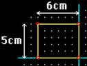
Setting the Profile
For the door to be created, record widths are designed as 5 cm and thicknesses as 6 cm. Profile dimensions to be selected will be 5/6 cm. Therefore, let's first define a profile with a width of 5 cm and a thickness of 6 cm.
-
Click on the Construction / Profile Editor row.
-
Enter 0.01 for the X / Y values in the grid section. These values represent the distances of the jump points on the grid from each other.
-
Click the New button in the lower right corner . Enter a name for the profile you want to create. You will see a profile of x = 6 cm y = 6 cm.
-
In the grid section, check the Lock to grid option, so you will be able to resize as whole numbers.
-
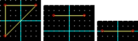
Changes you make in the Y axis in the profile will be reflected in the width of the frame edges and the thickness of the changes you make in the X axis.
-
The designed case edge thickness will be 6 cm and the width will be 5 cm. In this case, the frame can be created as designed by shortening the height of the profile by 1 cm and obtaining a profile with the dimensions x = 6, y = 5 cm. To do this, click the point in the upper right corner and move it to a lower point in the grid. Do the same with the dot in the upper left corner.
-
We need to move the origin point of this profile to the lower right corner in order to ensure that the frame edges extend from the nodes and form within the design boundaries.
-
Click the Set origin point icon.
-
Click on the lower right node of the profile.
-
Click the OK button. Against your Changed Under Profile for whether to register? message will come. Click on the Yes button.
Assigning Profile to Vault
-
Click the Properties line from the list that opens when you point to the safe and click the right mouse button .
-
The Case / Wing dialog will be displayed. Select the name of the profile you created from the Profile row in the parameters section in the middle .
-
Check the Blank option in the Type section .
-
When you click the OK button, the profile you have selected will be assigned to the safe and the safe will be emptied.
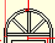
Drawing the Separators
-
Click on the Line Drawing / Separator .
-
Draw the splitter under the arch.
-
Draw a vertical separator up the center of the first separator.
-
Draw the right and left separators as well.
-
Click the Properties line from the list that appears when you hover over the separator and click the right mouse button .
-
The separator dialog will be displayed. Select the name of the profile you created from the Profile row in the parameters section in the middle .
-
When you click the OK button, the profile you selected will be assigned to the separator.
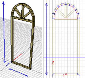
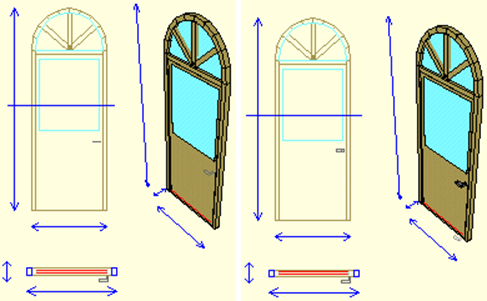
Drawing the Top Glass
When defining the profile for the safe, it was emptied by choosing the empty option as the type. Thus, instead of emptying the seat of the wing, the whole case can be emptied and the glass can be defined in the sections where there is no wing.
-
Click the Jump to Support / Object Points row.
-
Select the safe and horizontal separator (Jump points will be activated.).
-
Click the Line Drawing / Polygon .
-
Draw a semicircular polygon following the inner jumps of the arch. (As you draw, the polygon will be the same color as the case).
-
Click the Change / Extend line and select the polygon.
-
Enter x = 0, y = 0.02, z = 0.0 values from the dialog box that appears (You can do the extension by moving the extended part with the mouse, but it will be useful to enter values from the dialog box to ensure that the values are integers.).
-
The upper glass will become 3-dimensional.
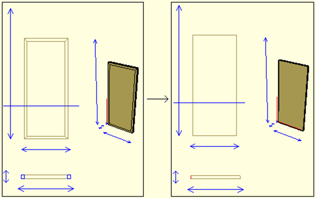
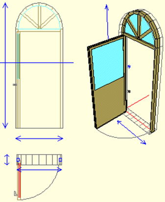
Drawing the Wing
Before starting to define the door leaf, the lower edge of the frame must be removed.
-
Click the Change / Keep Case-Wing Edges row.
-
Click on the lower edge of the case.
-
Click the Jump to Support / Object Points row.
-
Select the safe and horizontal separator (Jump points will be activated.).
-
Click the Line Drawing / Rectangular Case-Wing .
-
In the space inside the case, draw the wing with reference to the inner jumps of the pulley.
-
Click on the Support / Delete Free Jump Points row.
Adjusting the Profile of the Wing
The designed door wing has both full and empty parts with glass. For this reason, the wing should be filled first. For this;
-
Select the wing and enter its properties.
-
Check the Full option in the Types section .
There are still edges made of profiles around the wing you have filled. If you want the wing to stay that way, you can skip this section. If you want to use the wing as a fully filled edged wing, you need to assign an empty profile to the wing.
-
Click on the Construction / Profile Editor row.
-
Enter 0.01 for the X / Y values in the grid section. These values represent the distances of the jump points on the grid.
-
Click the New button in the lower right corner . Enter a name for the profile you want to create. You will see a profile of x = 6 cm y = 6 cm.
-
In the grid section, check the Lock to grid option, so you will be able to resize as whole numbers.
-
Click on the lower right corner profile point in the drawing window. Click the point that starts moving depending on the mouse, on the upper right point.
-
Do the same for the lower left corner profile point.
-
Click the set origin point icon in the lower left corner. Click on the middle point of the profile that becomes a straight line in the drawing window.
-
Click the OK button. Against your Changed Under Profile for whether to register? message will come. Click on the Yes button.
-
Enter the Properties section of the vault.
-
Select the profile you last created the profile for.
-
Click the OK button to exit the dialog.
Drawing the Glass of the Wing and Attaching This Glass to the Case
After the filled wing is formed, a space should be opened for the glass in the wing and glass should be defined in this space.
-
Click the Line Drawing / Polygon .
-
Draw the glass of the wing. If you determine your points as x, y values before drawing this polygon, and if you use the Coordinate System and Point Orientation while placing the points, the point placement will be easier and the chance of error will decrease.
-
Click on the Modify / Transform / Polygon-> Space Transform line.
-
Click the probe to the first polygon. There was a polygon-sized gap in the wing.
To define glass in the created space;
-
Click the Jump to Support / Object Points row.
-
Click the wing (Jump points in the space will be activated.).
-
Click the Line Drawing / Polygon .
-
Draw a gap-sized polygon in the gap in the wing.
-
Click the Change / Extend line and select the polygon.
-
Enter x = 0, y = 0.02, z = 0.0 values from the dialog box that appears (You can do the extension by moving the extended part with the mouse, but it will be useful to enter values from the dialog box to ensure that the values are integers.).
-
Your object will be created.
-
Click the Create / Set Up Frame-Wing Object Link line.
-
Click the wing first, then the glass.
Not
If the glass is formed at a distance from the wing on the Y axis, move the glass into the wing.
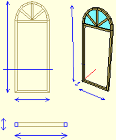
Drawing Arm and Connecting This Arm to the Case
To draw a door handle;
-
Click the Line Drawing / Polygon .
-
Draw the top view of the arm in plan view.
-
Click on the Change / Extend line.
-
Click on the polygon.
-
Enter the values x = 0, y = 0, z = 0.3 from the dialog box that appears (You can do the extension by moving the extended part with the mouse, but it will be useful to enter values from the dialog box to ensure that the values are integers.)
You need to connect the extended arm to the wing, because after the fastening process, when the wing is turned as if the arm is a part of the wing, it will rotate with the wing without distorting its placement on the wing. To connect the arm to the wing;
-
Click the Create / Set Up Frame-Wing Object Link line.
-
Click on the safe.
-
Click on arm.
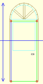
Determining the Wing Rotation Axis
You can determine which axis the wing will rotate around.
-
Click the Jump to Support / Object Points row.
-
Click Canada. The wing has become selected (Joints are visible. We will determine the rotation axis by jumping to these joints.).
-
Click the Change / Set Wing Axis row.
-
Click on the upper left node.
-
Click on the lower left node.
Not
Body Rotation Axis determination is the process of creating a line around which the case will rotate. This line can be drawn anywhere.
Adding a Parameter and Assigning This Parameter to the Wing
-
Click on the Construction / Add New Parameter row.
-
Enter the parameter name from the dialog that comes up.
-
Enter a number in degrees for the angle.
-
If the parameter is the opening angle , check the This Parameter is the door / window opening angle option.
-
Click the OK button.
To assign the added parameter to the wing;
-
Select the wing you want to open and enter its Properties .
-
Enter the name of the parameter you have created in the angle box or select the parameter by clicking the down arrow button next to the box.
-
Click the OK button.
Drawing the Void Polygon
-
Click the Jump to Support / Item Points row to capture the boundaries of your vault .
-
Click on the safe. Blue jump points have occurred around your vault.
-
Click on the Line Drawing / Gap Polygon .
-
Travel around your vault with the gap polygon, referring to the vault's outer jumps.
-
The gap polygon will close when you connect the last point with the first point.
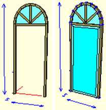
Adding New Material and Assigning This Material to the Door
-
Click on the Construction / Add New Material row.
-
In the dialog that comes up, click and hold the Color box and select the appropriate color.
-
If you activate the Transparent option, all objects covered with that material will be included in the ideCAD Architectural program transparently during rendering.
-
Name your material.
-
Click the Add button. The material will become active in the materials section at the bottom of the design tracking window.
-
Enter the Properties of the vault . Select the material you created in the Material section from the Parameters section .
-
Do the item assignment for all elements of the window.
Creating Plan, Section and View Drawings
These must be created before the dio is saved in order for the created door to be visible on the plan, section, and view pages.
-
You can create your plan automatically by clicking on the Construction / Create Plan line.
-
You can automatically create your cross section by clicking on the Construct / Create Section line.
-
You can create your view automatically by clicking on the Construction / Create Appearance line.
Later, you can make any changes you want in 2 dimensions in plan, section and views and make detailing.
Not
If the command create plan view is active and the section elevation is below the glass, the glass will not appear in the plan view. To eliminate this situation, you can turn off the "create plan view" command or you can move the section elevation up to cut the glass.
To raise the section elevation to cut the glass;
-
Click with the right mouse button on the section elevation in the facade view.
-
Select the Adjust section height command from the menu that opens. The section elevation will begin to move depending on the mouse.
Bring the section elevation high enough to cut the glass.
Drawing the Opening Spring
After the plan, section and views are created in 2 dimensions, if desired, 2 dimensional interventions can be made. Drawing an opening arc on doors and sometimes windows is one of these interventions.
-
Click the Line Drawing / Opening Spring .
-
Come to the plan window. In order to catch the starting and ending points of the opening arc, mark the lines associated with the jump to object points command. The start and end points of the lines will be marked and the cursor will catch these points.
-
Drag the cursor to the point where the opening arc will begin. Click when the cursor turns to OK. Get to the end point of the opening arc. Click when the cursor turns to OK. The opening arc will be drawn.
Next Topic