
How does ideCAD design eight bolts stiffened end plate connection according to AISC 358-16 & AISC 360-16?
-
Eight-bolt stiffened end plate connection is designed automatically according to the AISC 358-16 and AISC 360-16 by the ideCAD Structural.
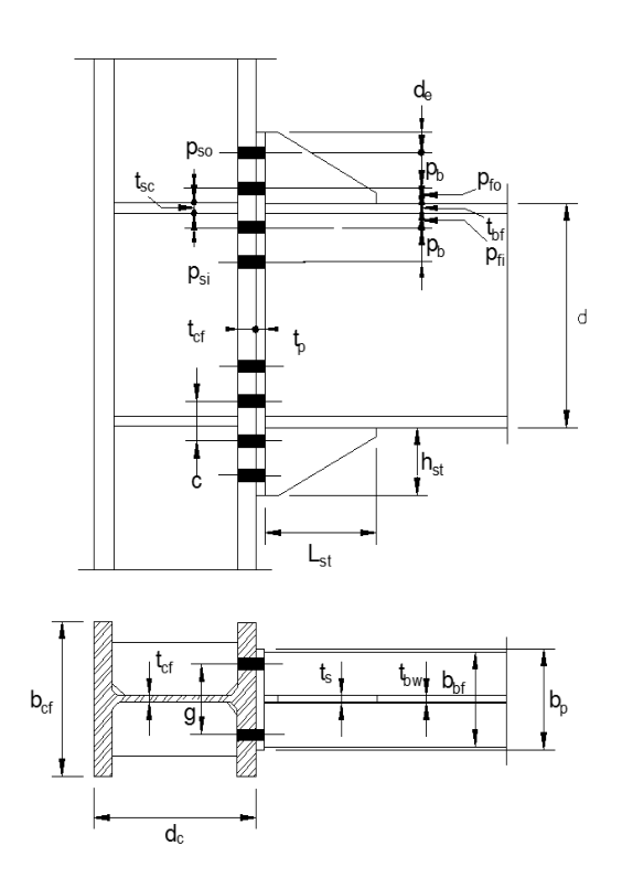
Lh = distance between plastic hinge locations, in. (mm)
Lst = length of stiffener, as shown in Figure 6.5, in. (mm)
Mpr = probable maximum moment at the plastic hinge, kip-in. (N-mm), given by Equation 2.4-1
Sh = distance from the face of the column to the plastic hinge, in. (mm)
Vgravity = beam shear force resulting from 1.2D + f1L + 0.2S (where f1 is a load factor determined by the applicable building code for live loads, but not less than 0.5), kips (N)
Vu = shear force at the end of the beam, kips (N)
bbf = width of beam flange, in. (mm)
d = depth of connecting beam, in. (mm)
tp = thickness of end-plate, in. (mm)
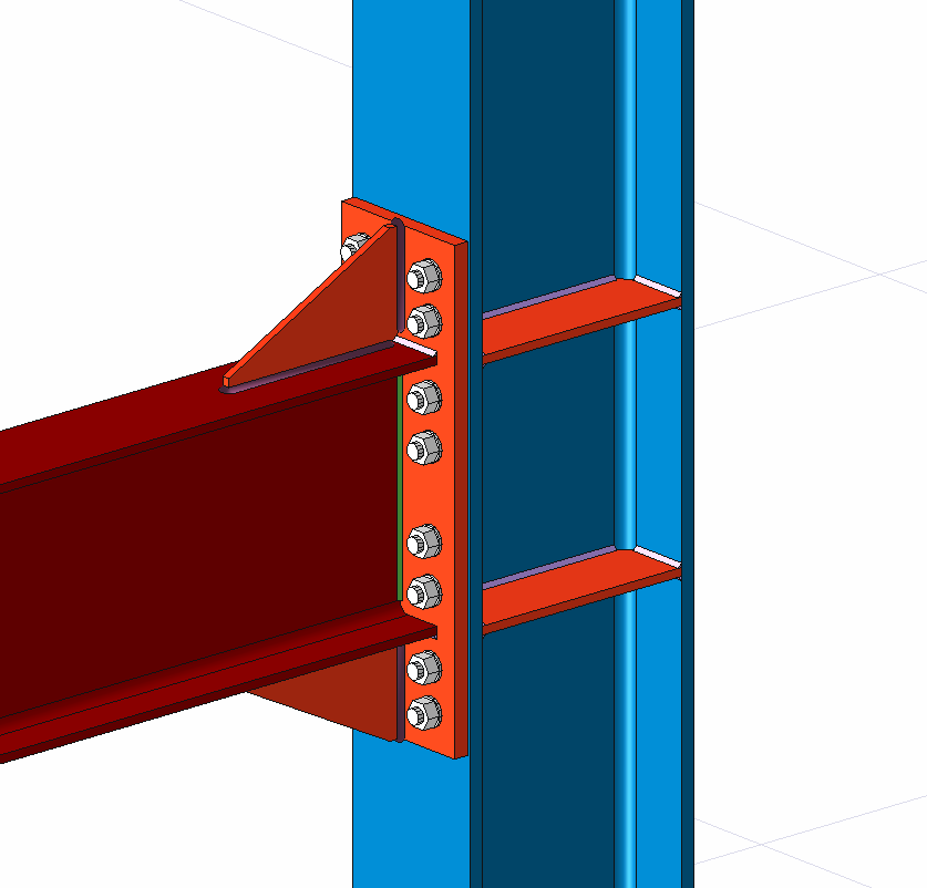
Eight bolt-stiffened end-plate connections consist of welding the beam to an end plate and bolting the end plate to a column flange.
Connection Design Parameters
Resistance factor for ductile limit state (Yielding Limit State):
Resistance factor for Non-ductile limit state (Rupture Limit State):
Distance from the face of the column to the plastic hinge, Sh, for four bolts stiffened end plate connection, is the Lst + tp
|
Parametric Limitations on Prequalification for Eight-Bolt Stiffened Connection |
||
|---|---|---|
|
Parameter |
Maximum
|
Minimum
|
|
tbf |
1 (25) |
9/16 (14) |
|
bbf |
121/4 (311) |
71/2 (190) |
|
d |
36 (914) |
18 (547) |
|
tp |
21/2 (64) |
3/4 (19) |
|
bp |
15 (381) |
9 (229) |
|
g |
6 (152) |
5 (127) |
|
pfi , pfo |
2 (51) |
15/8 (41) |
|
pb |
33/4 (95) |
31/2 (89) |
The probable maximum moment at the plastic hinge is given below, according to AISC 358-16.
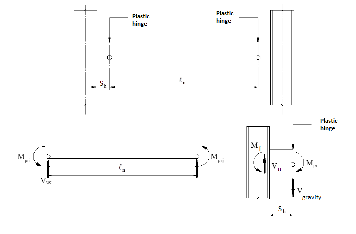
The moment at the face of the column, Mf., is calculated according to AISC 358-16 Eq. 6.8-1 given below.
The Vu used in the dimensioning of the joint is determined according to the equation in the above image by summing the shear force determined based on the yield state and the shear force calculated from the combination of 1.2G + 0.5Q + 0.2S on the plastic joint at the end of the beam.