
How does ideCAD design single plate connection according to AISC 360-16?
-
Single plate connection limit states and geometry checks are done automatically according to AISC 360-16.
-
The block shear limit state is checked automatically according to AISC 360-16.
-
Limit states of single plate flexural yield, plate flexural bucking, and weld strength are checked automatically.
Symbols
Ab: Non-threaded bolt web characteristic cross-sectional area
Ag: Gross area
An: Net cross-section area
Ae: Effective net cross-sectional area
Avg: Gross area under shear stress
Anv: Net area under shear stress
Ant: Net area under tensile stress
Aw: Cross-section web area
Cv: Coefficient of reduction for shear buckling
d: Characteristic diameter of the stem of the bolt (the diameter of the non-threaded stem of the bolt)
dh: Bolt hole diameter
Fy: Structural steel characteristic yield strength
Fu: Structural steel characteristic tensile strength
Fyb: Bolt characteristic yield strength
Fub: Bolt characteristic tensile strength
nsp: Number of slip planes
s: Distance between bolt-hole centers
L: Connector distance
Lc: The clear distance between bolt holes
Le: The distance from the center of the bolt hole to the edge of the assembled element
Leh: The horizontal distance from the center of the bolt hole to the edge of the assembled element
Lev: The vertical distance from the center of the bolt hole to the edge of the assembled element
t: Plate thickness
Rn: Characteristic strength
Rnt: Characteristic tensile strength
Rnv: Characteristic shear strength
Ubs: A coefficient considering the spread of tensile stresses
Connection Geometry
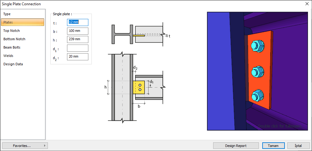
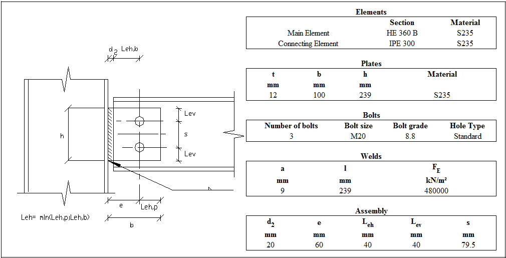
Geometry Checks
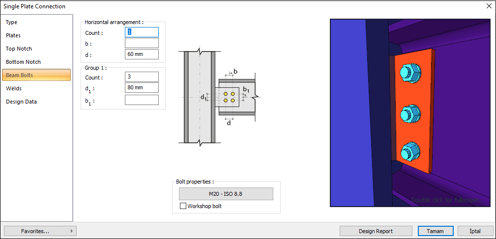
Bolt Spacing
The distance between the centers of bolts is checked per AISC 360-16.
|
smin ≥ 3d |
AISC 360-16 J3.3 |
|
|
|
s |
79.5 mm |
|
|
|
d |
20 mm |
s =79.5 mm > smin = 3*20=60 mm |
√ |
Horizontal Edge Distance
The distance from the center of the hole to the edge of the connected part in the horizontal direction is checked per AISC 360-16.
|
Leh ≥ Le-min |
AISC 360-16 J3.4 |
|
|
|
Leh |
40 mm |
Leh ≥ 2d = 2 * 20 = 40 mm conformity check for application |
√ |
|
Le-min |
26 mm |
Minimum distance check according to AISC 360-16 Table J3.4 |
√ |
Vertical Edge Distance
The distance from the center of the hole to the edge of the connected part in the vertical direction is checked per AISC 360-16.
|
Lev ≥ Le-min |
AISC 360-16 J3.4 |
|
|
|
Lev |
40 mm |
Leh ≥ 2d = 2 * 20 = 40 mm conformity check for application |
√ |
|
Le-min |
26 mm |
Minimum distance check according to AISC 360-16 Table J3.4 |
√ |
Weld Size
The minimum size of fillet welds is checked according to AISC 360-16 Table J2.4
|
w ≥ wmin |
AISC 360-16 Table J2.4 |
|
|
|
w |
12.73 mm |
|
√ |
|
wmin |
5 mm |
AISC 360-16 Table J2.4 |
√ |
Erection Stability
|
L ≥ hb/2 |
|
|
|
|
L |
239 mm |
|
|
|
hb |
248.6 mm |
L=239 > 248.6/2=124.3 mm |
√ |
Strength Checks
Bolt Shear at Beam
-
The calculation is made using the Elastic method, one of the methods selected in the steel analysis settings tab. For the details of this check, AISC Manual 14th 7-8 is used as a reference.
-
In this check, the operation is performed on half of the symmetry axis and is calculated to form a force pair with the required force.
|
Ab |
|
|
Fn=Fnv |
|
|
Rn |
|
|
Rn / Ω |
|
|
Required |
Available |
Check |
Result |
|---|---|---|---|
|
34,318 kN |
56,549 kN |
0.607 |
√ |
Bolt Bearing on Beam
The bearing strength limit states of the plate, which are “shear tear out” and “ovalization of bolt hole” for both end and inner bolts, are checked according to AISC 360-16.
|
dh |
20+2=22 mm |
|
|
Lc,edge |
|
|
|
Rn |
|
AISC 360-16 J3-6a
|
|
Rn-edge |
|
|
|
Lc,spacing |
|
|
|
Rn-spacing |
|
|
|
Rn |
|
|
|
Rn / Ω |
|
|
|
Required |
Available |
Check |
Result |
|---|---|---|---|
|
68,159 kN |
185,487 kN |
0.367 |
√ |
Bolt Bearing on Plate
Bearing strength limit states of the connection plate that are “shear tear out” and “ovalization of bolt hole” for both end and inner bolts are checked according to AISC 360-16.
|
dh |
20+2=22 mm |
|
|
Lc,edge |
|
|
|
Rn |
|
AISC 360-16 J3-6a |
|
Rn-edge |
|
|
|
Lc,spacing |
|
|
|
Rn-spacing |
|
|
|
Rn |
|
|
|
Rn/Ω |
|
|
|
Required |
Available |
Check |
Result |
|---|---|---|---|
|
68,159 kN |
284,75 kN |
0.239 |
√ |
Plate Shear Yield
The shear strength of connecting elements in shear is the minimum value obtained according to the limit states of shear yielding and shear rupture. Shear yielding is checked according to AISC 360-16.
|
Ag |
|
|
|
Fy |
235.359 N/mm2 |
|
|
Rn |
|
AISC 360-16 J4-3 |
|
Rn/Ω |
|
|
|
Required |
Available |
Check |
Result |
|---|---|---|---|
|
68,159 kN |
270 kN |
0.252 |
√ |
Beam Shear Rupture
The shear strength of connecting elements in shear is the minimum value obtained according to the limit states of shear yielding and shear rupture. Shear rupture is checked according to AISC 360-16.
|
Anv |
|
|
|
Fu |
362.846 N/mm2 |
|
|
Rn |
|
AISC 360-16 J4-3 |
|
Rn / Ω |
|
|
|
Required |
Available |
Check |
Result |
|---|---|---|---|
|
68,159 kN |
176.213 kN |
0.387 |
√ |
Plate Shear Rupture
In the case of the block shear limit state, the net area rupture of the tensile plane of the connection part is checked according to AISC 360-16.
|
Anv |
|
|
|
Fu |
362.846 N/mm2 |
|
|
Rn |
|
AISC 360-16 J4-3 |
|
Rn / Ω |
|
|
|
Required |
Available |
Check |
Result |
|---|---|---|---|
|
68,159 kN |
218.143 kN |
0.312 |
√ |
Plate Block Shear Rupture
The block shear limit state is checked according to AISC 360-16. All block shear modes combined with tensile failure on one plane and shear failure on a perpendicular plane are checked according to AISC 360-16.
|
Ag |
|
|
|
Anv |
|
|
|
Ant |
|
|
|
Fy |
235.359 N/mm2 |
|
|
Fu |
362.846 N/mm2 |
|
|
Ubs |
1.0 |
|
|
|
|
|
|
Rn |
|
AISC 360-16 J4-3 |
|
Rn / Ω |
|
|
|
Required |
Available |
Check |
Result |
|---|---|---|---|
|
68,159 kN |
229.569 kN |
0.297 |
√ |
Plate Flexural Buckling
Single plate material slenderness check.
|
Fy |
235.359 N/mm2 |
|
|
t |
12 mm |
Material thickness |
|
a |
60 mm |
Distance from the support to the first bolt |
|
L |
239 mm |
Length of material |
|
λ |
|
|
|
Required |
Available |
Check |
|---|---|---|
|
≤0.70 |
0.17 |
√ |
Plate Flexural Yield
Single plate material flexural yielding check.
|
dp |
239 mm |
Length of material |
|
Fy |
235.359 N/mm2 |
|
|
tp |
12 mm |
Material thickness |
|
a |
60 mm |
Distance from the support to the first bolt |
|
Rn |
|
|
|
Rn / Ω |
|
|
|
Required |
Available |
Check |
Result |
|---|---|---|---|
|
68,159 kN |
223.92 kN |
0.304 |
√ |
Weld Strength at Support
|
w |
12.73 mm |
Weld leg size |
|
FE |
480 N/mm2 |
Weld material tensile strength |
|
l |
239 mm |
Weld length |
|
e |
60 mm |
Eccentricity |
|
Rn |
|
|
|
Rn / Ω |
|
|
|
Required |
Available |
Check |
Result |
|---|---|---|---|
|
68,159 kN |
421.131 kN |
0.162 |
√ |
Next Topic