
-
In each step of the push analysis, displacements for each direction and mode are automatically calculated.
The increment of displacement of any (s) degree of freedom (or node) of the conveyor system for a typical n'th natural vibration mode in any i'th pushing step between two consecutive plastic joint formation, u sec (i) is expressed by the following equation are being.
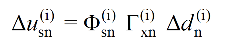
In this relation, Φ sec (i) denotes the amplitude of the (s) degree of freedom of the nth mode shape determined by considering the plastic section configuration at that step in the (i)th push step. This valueIt is an element of the matrixn(i)which means the mode shape vector of the structure, which is explained in theModal Characteristics Determination. In this matrix, each element represents the mod shape amplitude of a node.
The Γ xn (i) value ( X ) is the modal contribution factor calculated in the i'th step of the thrust analysis for a typical n'th natural vibration mode in the earthquake direction. Calculation of this value It is explained in the Modal Characteristics Determination
Δd n (i) is the modal displacement increment calculated in step i of the thrust analysis for a typical n'th natural vibration mode. Determination of Modal Pseudo-Acceleration, Modal Displacement Increment and Constant Scale Factor are explained in detail in the title.
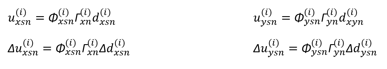
The above equation can be expressed in the i'th repulsion step of the repulsion analysis for an earthquake in the (X) direction and as the displacement increment for a typical n'th natural vibration mode, Δu xsn (i) . Similarly, for an earthquake in the (X) direction, the modal displacement increment, Δd xn (i), and the mode shape amplitude can be written as Φ xsn (i) .
(X) and (Y) in the seismic line in the i-th thrust step, a typical n-th carrier system for natural vibration mode of any one (s) displacement increments of node, Δ is xsn (i) and Δ is ysn (i) the location The replacement values u xsn (i) and u ysn (i) can be calculated by the following equations.
With this process, the deformations of the structure for each mode are obtained at the end of the i th pushing step. These changes are then combined with the CQC rule, resulting in a modified system to perform modal analysis in the next step.