How does ideCAD control the maximum spacing of moderately ductile beams according to AISC 341-16?
-
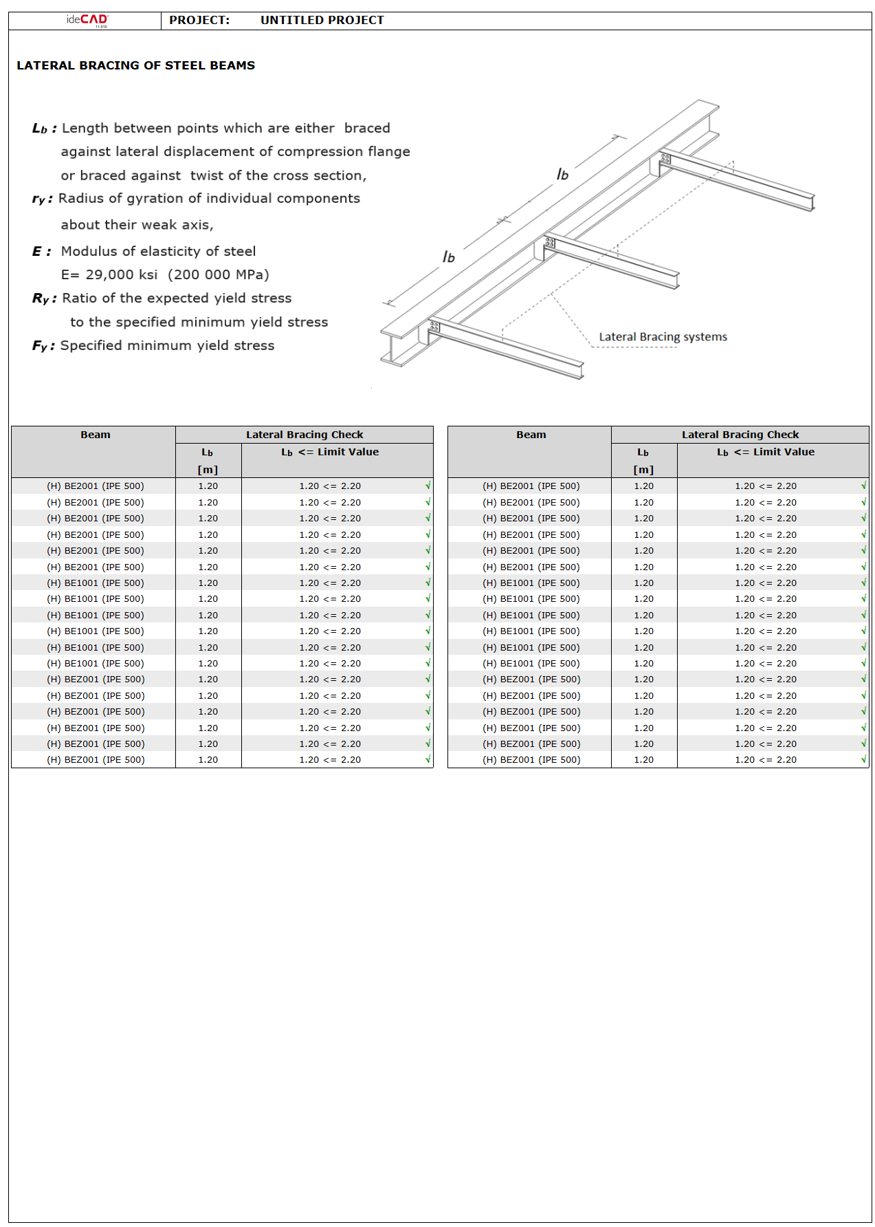
Maximum spacing of beam bracing systems is controlled automatically and reported with steel beam reports.
Symbols
Fy = Specified minimum yield stress
Ry = Ratio of the expected yield stress to the specified minimum yield stress, Fy
Mr = Required flexural strength, kip-in. (N-mm)
Lb = Length between points which are either braced against lateral displacement of compression flange or braced against twist of the cross-section, in. (mm)
ry = Radius of gyration about y-axis, in. (mm)
Z = Plastic section modulus about the axis of bending, in.3 (mm3)
αs = LRFD-ASD force level adjustment factor 1.0 for LRFD and 1.5 for ASD
E= Modulus of elasticity of steel = 29,000 ksi (200 000 MPa)
The requirements for stability bracing of beams designated as moderately ductile members and highly ductile members are a function of the anticipated levels of inelastic yielding as explained in AISC 341-16 Commentary Section D1.1 for members with these designations.
This control is done automatically and reported on the beam elements of the frame.