
ICONS
a 1 (X,k) = modal pseudo-acceleration [m/s2] of the first mode modal single degree of freedom system at the kth push step for earthquake direction [m/s2]
d 1 (X,k) = (X) earthquake modal displacement of the modal single degree of freedom system belonging to the first mode in the kth thrust step for the kth thrust for the earthquake direction[m]
m i = the total mass of the i th floor
m ix1 (X,1) = (X) the first thrust in the x-axis direction for the earthquake directionith floor modal effective mass [t]
m tx1 (X,1) calculated accordingto the constant mode shape determined in step and never changed during the thrust calculation
= (X) modal effective mass of the base shear force calculated according to the constant mode shape determined in the first thrust step in the x-axis direction for the earthquake direction and never changed during the thrust calculation [t]
m iy1 (X,1) = (X) for the earthquake direction i'th floor modal effective mass calculated according to the constant mode shape determined in the first thrust step in the y-axis direction and never changed during the thrust calculation [t]
m iθ1 (X,1) = (X) for the earthquake direction in the first thrust step around the z-axis The ith floor calculated according to the fixed mode shape determined and never changed during the thrust calculation
modal effective mass moment of inertia [tm2]
u ix1 (X,k) = (X) displacement calculated in the x-axis direction at the ith floor at the kth thrust step for the earthquake direction [m]
u Nx1 (X,k) = (X) displacement [m] calculated in the x-axis direction at the Nth floor (at the top of the building) at the kth push step for the earthquake direction
V tx1 (X,k) = (X) the base shear force calculated in the x-axis direction at the kth push step for the earthquake direction [kN]
Δa 1 (X,k) = modal pseudo-acceleration increment of the modal one degree of freedom system of the first mode at the kth push step for the earthquake direction (X)[m / s 2 ]
Δd 1 (X, k) = (X) k earthquake direction of the 'th pushing step the first mode of modal single degree of freedom system ' s modal displacement of [m]
Δf ix1 (X, k) = (X ) k earthquake direction of the 'th thrust step i' th floor, the x-direction acting seismic load increment [kN]
Δf iy1 (X, k) = (X) k earthquake direction of the 'th thrust step i' th floor acting along the Y axis earthquake load increment [kN]
Δf iθ1 (X,k) = (X) earthquake load increment acting in the z axis direction at the i th floor at the k th thrust step for the earthquake direction [kN]
Φ ix1 (1) = the constant mode shape determined in the first thrust step at the i th floor and never changed during the thrust calculation ' x-direction amplitude of
Φ iy1 (1) = y-direction amplitude of constant mode shape determined in the first push step at the i'th floor and never changed during the push calculation
Φ iθ1 (1) = determined in the first push step at the i'th floor and throughout the push calculation no unaltered constant mode shape 's rotational amplitude of the z axis
Γ1 (X,1) =modal contribution factorcalculated accordingto theconstant mode shapedetermined in the first impulse step for the earthquake direction and which is not changed during the impulsecalculation
5.6.3. Constant Single Mode Pushover Analysis Method
In the Fixed Single Mode Push Method , the earthquake load increments acting on the floors at each push step in the direction of the considered earthquake are defined in proportion to the fixed mode shape , which is determined in the first step after the non-earthquake loadings and never changed during the push calculation . As a result of the thrust calculation, the thrust curve whose coordinates are the peak displacement – the base shear force is obtained. Then, with the coordinate transformation applied to this curve , the modal capacitance diagram whose coordinates are modal displacement – modal pseudo-accelerationobtained. In the last stage of the calculation, this diagram is taken as a basis for calculating the modal displacement demand under the defined earthquake effect and accordingly the internal force and plastic deformation demands occurring in the carrier system. Details of the method are given in Appendix 5B .
5B.1. OBTAINING MODAL CAPACITY DIAGRAM BY CONSTANT SINGLE MODE PUSHOVER ANALYSIS METHOD
5B.1.1 – In the constant single mode pushover analysis method , the earthquake load increments acting on the floors at the kth thrust step in the earthquake direction (X) considered are calculated according to the fixed mode shape determined in the first step after the non-earthquake loadings and never changed during the thrust calculation. are expressed in terms of their floor modal effective mass :

Here, m ix1 (X,1) , m iy1 (X,1) and m iθ1 (X, 1) are the first mode calculated in the first step (k=1) of the floor effective masses given by Equation (4B.2) in ANNEX 4B . are the equivalents (n = 1) :

In these equations, Γ 1 (X,1) is the modal contribution factor calculated from Eq.(4B.1) in the first impulse step for the earthquake direction (X) and the first vibration mode considered .
5B.1.2 – Unknown magnitude at the kth push step defined between two consecutive hinge formations , modal pseudo-acceleration increment Δa 1 (X,k ) in Equation (5B.1) of the modal single degree of freedom system of the first mode ) is . This size is calculated from the yield condition defined in 5.3.1 of a new plastic hinge formed at the end of each step . The resulting modal pseudo-acceleration increment is added to the pseudo-acceleration value found at the end of the previous step to obtain the cumulative modal pseudo-acceleration a 1 (X,k) at the end of the kth step . In traditional push calculation a 1 (X,k), (X) is obtained from Equation (5B.3) written for the base shear force Vtx1 (X,k) in the earthquake direction :

Located in this connection base shear modal effective mass m TX1 (X, 1) in the direction of x-axis Eq. (5B.2) from first mode in a first thrust step ACCORDING defined and fixed during the push account taken as floor modal effective is the sum of the masses m ix1 (X,1) on all floors.
5B.1.3 – The modal displacement d 1 (X)k of the modal single degree of freedom system belonging to the first mode can be calculated from the horizontal displacement obtained in the x direction at any i th floor from the thrust calculation. The traditional thrust calculation uses the peak displacement at the N'th floor for this purpose:

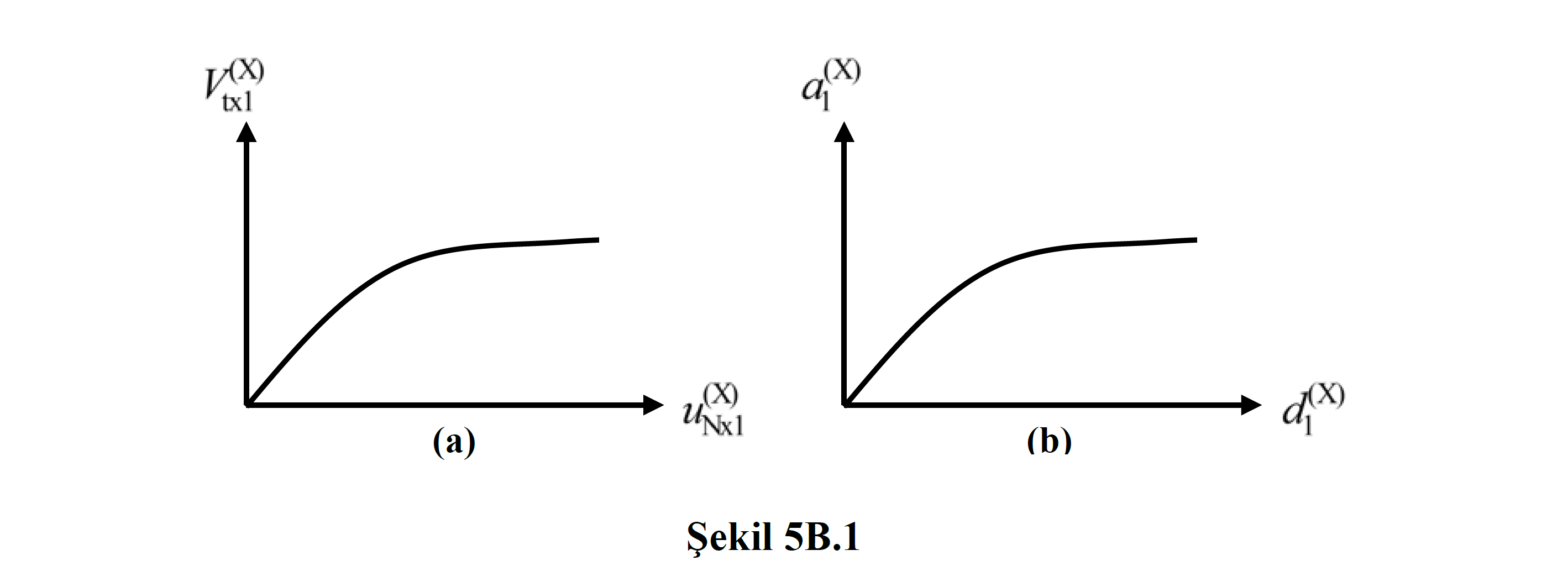
5B.1.4 – In the conventional thrust calculation, firstly , the thrust curve is drawn as the base shear force – peak displacement relationship ( Figure 5B.1a ) and then the coordinates of this curve are converted according to Equation (5B.3) and Equation (5B.4). single degree of freedom system modal formula modal acceleration pseudo-modal displacement relationship as a modal capacity diagram is obtained ( FIG 5b.1b ).
5B.1.5 – In the conventional thrust calculation, since the modal displacement is obtained at each step depending on the constant mode shape of the linear system in the initial step with Eq.(5B.4) , in order to partially eliminate the approximation, it can be obtained at any kth thrust step. The displacement increment obtained can be taken as the amplitude of the variable mode shape at approximately that step . In this context , the equation in Eq.(5B.5) is written for the degrees of freedom in the x-direction at a typical i'th floor:

In this case the modal displacement Eq. (5B.4) 'in order that, irrespective the peak displacement, Eq. (5B.6) may be obtained as follows:

Wherein Γ 1 (x, k) , Eq. (5B.5) from utilizing the defined mode of approximately Eq. (4B.1) with each thrust approximately calculated in step modal contribution factor 'is.
5B.1.6 - stopped şekildeğiş of vertical load bearing system consisting second order effects 's buildings may be important where, Constant Single Mode Pushover Analysis Method in the bottom because it is based on shearing forces, these effects can not be compatible format into account, 5B.2 from the Adaptive Single Mode Pushover Analysis Method should be used.