ICONS
a 1 (X,k) = modal pseudo-acceleration of the first mode modal one degree of freedom system at the kth push step for the earthquake direction [m/s 2 ]
d 1 (X,k) = (X) modal displacement of the modal single degree of freedom system belonging to the first mode at the kth thrust step for the earthquake direction [m]
m ix1 (X,k) = (X) free vibration calculation at each kth thrust step in the x-axis direction for the earthquake directioni'th floor modal effective mass calculated according to thevariable mode shape renewed with[t]
m iy1 (X,k) = (X) ith floor modal effective mass calculated according to the variable mode shape , which is renewed with the free vibration calculation at each kth thrust step in the x-axis direction for the earthquake direction [t]
m iθ1 (X,k) = (X) i th floor modal effective mass moment of inertia [tm2]
u ix1 (X,k) = (X) earthquake direction calculated according to the variable mode shape , which is renewed with the free vibration calculation at each kth thrust step in the x-axis direction for the earthquake direction displacement [m]
Δa 1 (X,k) calculated along the x-axis at the i-th floor at the kth push step
= (X) modal pseudo-acceleration increment of the first mode modal single degree of freedom system at the kth thrust step for the earthquake direction [m/s 2 ]
Δd 1 (X,k) = the kth for the (X) earthquake direction modal displacement of the first mode modal single degree-of-freedom system in the push step [m]
Δf ix1 (X,k) = (X) earthquake load increase acting in the x-axis direction at the i'th floor at the kth push step for the earthquake direction [kN]
Δf iy1 (X,k) = (X) earthquake load increase acting in the y axis direction at the i th floor at the k th push step for the earthquake direction [kN]
Δf iθ1 (X,k) = for earthquake direction (X) earthquake load increase acting in z axis direction at i th floor at k th push step [kN]
Δu ix1 (X,k) = (X) for earthquake direction k 'in th thrust step i' This displacement increment calculated in accordance with the x-th layer [m]
Δ of iy1 (X, k) = (X) k earthquake direction of the 'th thrust step i' th floor y-axis is displacement increment calculated in accordance with [m]
Δu iθ1 (X,k) = displacement increment calculated in the z-axis direction at the i'th floor at the kth thrust step for the earthquake direction [m]
Φ ix1 (k) = The x-direction amplitude of the variable mode shape at each kth thrust step at the i'th floor with free vibration calculation
Φ iy1 (k) = the variable mode shape renewed with the free vibration calculation at each kth thrust step at the i'th floor The amplitude of in the y direction
θ iθ1 (k) = the amplitude of the variable mode shape in the z direction
Γ 1 (X,k) = (X) each for the earthquake direction calculated according to the variable mode shape , which is renewed by the calculation of free vibration at a kth thrust step.modal contribution factor
ω 1 (k) = First mode natural angular frequency [rad/s] found from the free vibration calculation, which is renewed at each k 'th impulse step
5.6.4. Adaptive Single Mode Pushover Analysis Method
In the Variable Single-Mode Pushing Method , the earthquake load increases acting on the floors in the direction of the considered earthquake and the floor displacement increments compatible with them , the variable mode obtained from the free vibration calculation , which is renewed in each push step after non-earthquake loadings, taking into account the plastic hinges formed before. are defined in proportion to their shape . In this method , the modal capacitance diagram is obtained directly without the need to draw the thrust curve specified in 5.6.3 . The final stage of the calculation is as specified in 5.6.3 . Details of the method are given in Appendix 5B .
5B.2. ACQUISITION OF MODAL CAPACITY DIAGRAM BY ADAPTIVE SINGLE MODE PUSHOVER ANALYSIS METHOD
5B.2.1 - Adaptive single mode pushover analysis method 'in, considering the received (X) earthquake direction plies effect of earthquake load increments , earthquakes each subsequent from external loading kth thrust variable obtained from the free vibration account updated in step mode shape "According calculated floor expressed in terms of modal effective masses :

M wherein ix1 (X, k) , m iy1 (X, k) and m iθ1 (X, k) of each k '-th pushing step, then depending on the form of the free vibration mode refreshed in step EK 4B from Eq. (4B. are the first mode equivalents of the effective masses calculated by 2) (n=1):

In these equations, Γ 1 (X,k) is the modal contribution factor calculated from Eq.(4B.1) depending on the first vibration mode renewed at each k th impulse step for the earthquake direction (X) considered .
5B.2.2 - Each push kth step, the above Eq. (5B.7) from the floor seismic load increments 's deck formed under the influence of displacement increments of Eq. (5B.9) is obtained:

5B.2.3 - Eq. (5B.7) which is located k 'of th thrust step modal pseudo-acceleration increment Δ A 1 (X k) by Eq. (5B.9) , located in modal displacement increments expressed as a dimensionless one The step-by-step linear relationship between (X,k) is given in Eq.(5B.10) :

Here, ω is the first mode natural angular frequency found from the free vibration calculation, which is renewed at each k th thrust step of the 1 (k) carrier system .
5B.2.4 – Modal pseudo-acceleration increment Δa 1 (X, X, ) of the first mode in Equation (5B.7) of the modal single degree of freedom system as an unknown magnitude at the k th thrust step defined between two successive hinge formations . k) can be taken ( force based calculation ). However, instead, it should be preferred to take the modal displacement increment Δd 1 (X,k) in Eq.(5B.9) as an unknown quantity in order to allow direct calculation of internal forces ( displacement based calculation ). In both cases the modal increment is taken as unknown., will be calculated from the yield condition defined in 5.3.1 of the new plastic hinge formed at the end of the kth step . After calculating the unknown modal increment, the other modal increment is also obtained from Eq.(5B.10) .
5B.2.5 – The modal pseudo-acceleration and modal displacement increments obtained in the kth push step are summed up with the values obtained at the end of the previous step, and the cumulative values of these quantities are obtained as in Eq.(5B.11) :

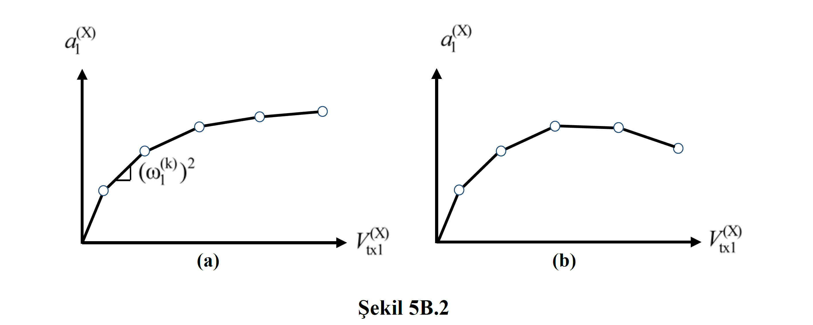
Thus, in the variable load or displacement distribution thrust method , the modal capacitance diagram is obtained directly without the need to draw the thrust curve . In this diagram , the slope of the line segment representing the step-by-step linear behavior at the k'th push step between two successive hinge formations is equal to (ω 1 (k) ) 2 according to Eq (5B.10) ( Fig . 5B.2a ).
5B.2.6 – In case the geometric stiffness matrix representing the second order effects is taken into account in the free vibration calculation, (ω 1 (k) ) 2 in Eq.(5B.10) , in other words, the slope of the modal capacity diagram, in the carrier system can be obtained as negative values in the forward pushing steps where plastic deformations increase ( Figure 5B.2b ).