
Various steel structural elements are used when defining steel structures. In order for the steel construction elements used to work together, they are connected to each other with steel connections.
Connection Definition
Connections are selected by clicking on the connection icon to be applied, elements in plan, perspective or any working plane.
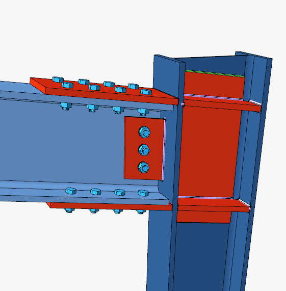
Connection Image
Connections appear instantly in 3D. In the 3D view, operations such as panning, zooming, and rotating can be performed. The changes made in the connections can be viewed simultaneously in 3D view.
The 3D image is rotated by moving the mouse up and down, left and right on the 3D image while holding down the left mouse button. If the mouse is moved up and down while holding down the right mouse button, the image zooms in and out. The image moves in the XY plane (grid plane) if the mouse is moved on the 3D image while holding down the Ctrl key and the left mouse button on the keyboard, and the YZ plane (plane perpendicular to the grid plane) if the image is moved by holding down the Ctrl key and the right mouse button.
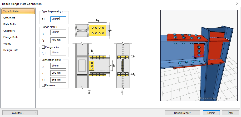
Connections Properties and Connections Dialog
After any connection is created, if the connection is double clicked, a dialog will appear where the properties of the connection can be changed.
Changes made in the dialog can be viewed instantly in the 3D view included in the dialog.
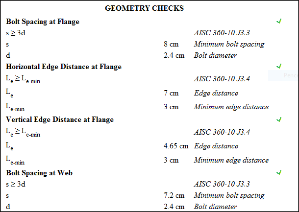
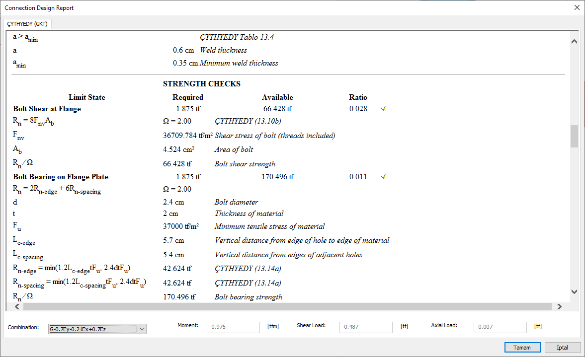
Design Reports
Design reports of the calculated connections can be displayed with the Design Report button in the connection dialog.
Connection Types
Connections are designed as bolted and/or welded.
Loads and Downloads
The program takes the loads required for the connection calculations from the analysis results. The joint effects consist of axial and shear forces and bending moments taken from the connections.
Bolts
Parameters related to bolt class, diameter, hole type, hole diameter, number of bolts, placement geometries of bolts can be set in the connections dialog, according to the connection type in the bolts tab.
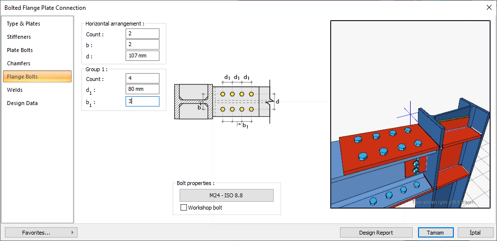
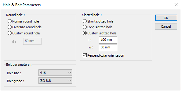
Bolt properties:
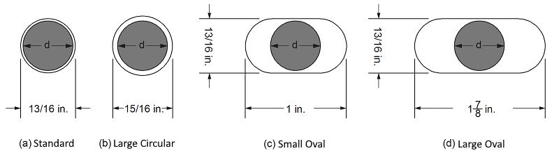
Bolt diameter, bolt class and bolt hole type are determined in the bolt properties dialog.
Continuity Plates
The purpose of the continuity plates is to support the column heads in the column-beam joints and to ensure the continuity of the beam head. Continuity plates are used for reinforcement in order to bend the column head and prevent column stem flow / wrinkle. In the program, the sheets are selected in the connection settings dialogs and their properties are set.
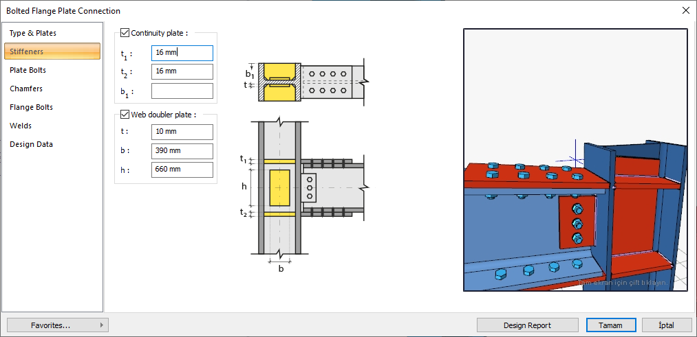
Web Doubler Plate
If the column body thickness is insufficient, web doubler plates are used to meet the shear effect of the panel area. The selection of whether or not to use rweb doubler plate and, if used, the determination of its properties are made in the connection settings dialog.
Chamfers

For easy assembly of the plates in the field, the use of slope, slope type and geometric properties are determined in the connection settings dialog.
Welds
Resources are found in the join properties dialog. The source type for all joint types is determined automatically by the program. It also checks if the program resource type is not available.
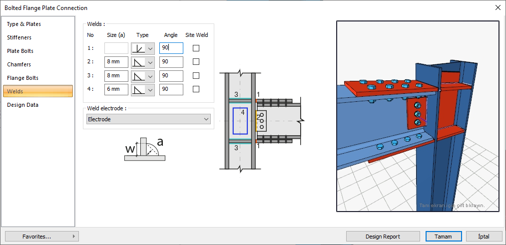
Welding Geometry
Welding geometry is determined automatically by the program. These properties can be changed to easily determine the joint properties. Geometry features are in accordance with industry standards and in the form specified in AISC.
Corner Weld (Design Input)
The main element in the weld connection may have less strength than the weld strength. This requirement is controlled for all welded connections.
FEXX = Electrode strength
Full Penetration Bulk Welding (Design Input)
Full penetration butt welding is designed to use all the strength of the main element as a result of the welding of the welded element completely. According to the American Welding Society (AWS), the metal material used as the electrode must have the same properties as the main element metal material. The program compares the beam, column and connection material to determine the welding electrode. If the materials are not compatible, the program warns the user that the source control is wrong. The properties of the main element and the electrode must be the same. An abbreviated list of compatible materials is available in AISC Specification J2.6.
Weld Limits
The program determines the lower limits of the weld sizes according to AISC restrictions. The program warns the user when the limits regarding resource dimensions are exceeded.
Next Topic