
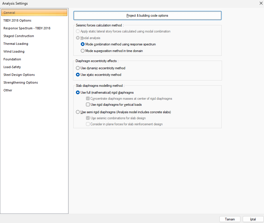
In accordance with Codes, the modeling of slabs as fully rigid or semi-rigid is determined by user selection.
In buildings with different types irregularities, story slabs have to be modeled with two-dimensional plate (membrane) or shell finite elements to show that they can safely transfer earthquake forces between vertical structural system elements in their own planes.
If different types irregularities have been confirmed, selection of semi-rigid diaphragm should be made by user.
The analysis model of the slabs modeled by selecting the fully rigid diaphragm is created automatically.
The analysis model of the slabs modeled by selecting the semi-rigid diaphragm is created automatically.
İnternational Design Codes
ASCE 7-16 : Modeling Story Slabs per ASCE 7-16 with ideCAD
TSC 2018 : Slab Modelling
Story floors;
(a) transfer the inertia forces created by the masses on the floors due to the earthquake accelerations, together with the beams, if any, to the vertical structural system elements thanks to their high in-plane stiffness,
(b) at the same time, and generally more importantly, are horizontal bearing system elements that enable the earthquake loads acting on the building to be distributed among vertical bearing system elements according to their rigidity. It is essential that floors, which may include gaps of various sizes, be modeled appropriately in order to accurately determine the load transfer in their own planes.
According to Codes in buildings where there are different types irregularities and / or floors are not intended to operate as a rigid diaphragm, and in flat slab systems, floors will be modeled with two-dimensional finite elements as a semi-rigid diaphragm.
It is essential to provide sufficient in-plane rigidity and strength in the floors of the transition floors, which are involved in the transition from normal floors to rigid basement floors and have to suddenly transfer all or most of the inertia forces that occur in the upper floors to the perimeter shearwalls in the basement floors. This condition is also valid for other transition floors where sudden stiffness changes are made for other reasons.
Referance: Seismic design of reinforced concrete Buildings, Jack Moehle, 2015 by McGraw-Hill Education.
Regardless of any irregularity control, floors in normal story and rigid basement story transitions are modeled with two dimensional shell finite elements (shell).
In terms of horizontal stiffness, the upper part (normal floors) and the lower part (basement floors), which is much more rigid, have very different properties in terms of dynamic behavior and strength. As can be seen in the shearwall shear diagram shown below, the shear force changes in the transition layer. The floor in the transition story must have sufficient rigidity and strength to carry out the load transfer caused by this shear force difference. This situation causes the forces to be transferred to the floor and horizontal load-bearing system to increase. For this reason, all of the structures with a transition layer should be solved with semi-rigid diaphragm acceptance.
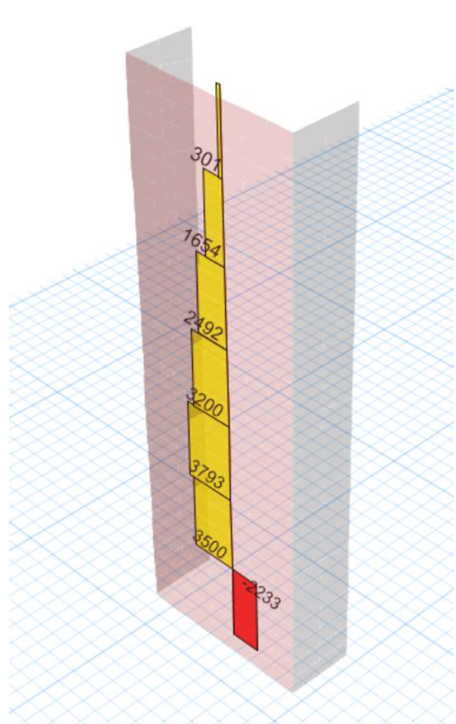
In the picture below, there is a shear force diagram of a structure with a rigid basement. As can be seen, the shear force has changed direction at the floor level in the transition floor from the normal floors to the rigid basement floor.
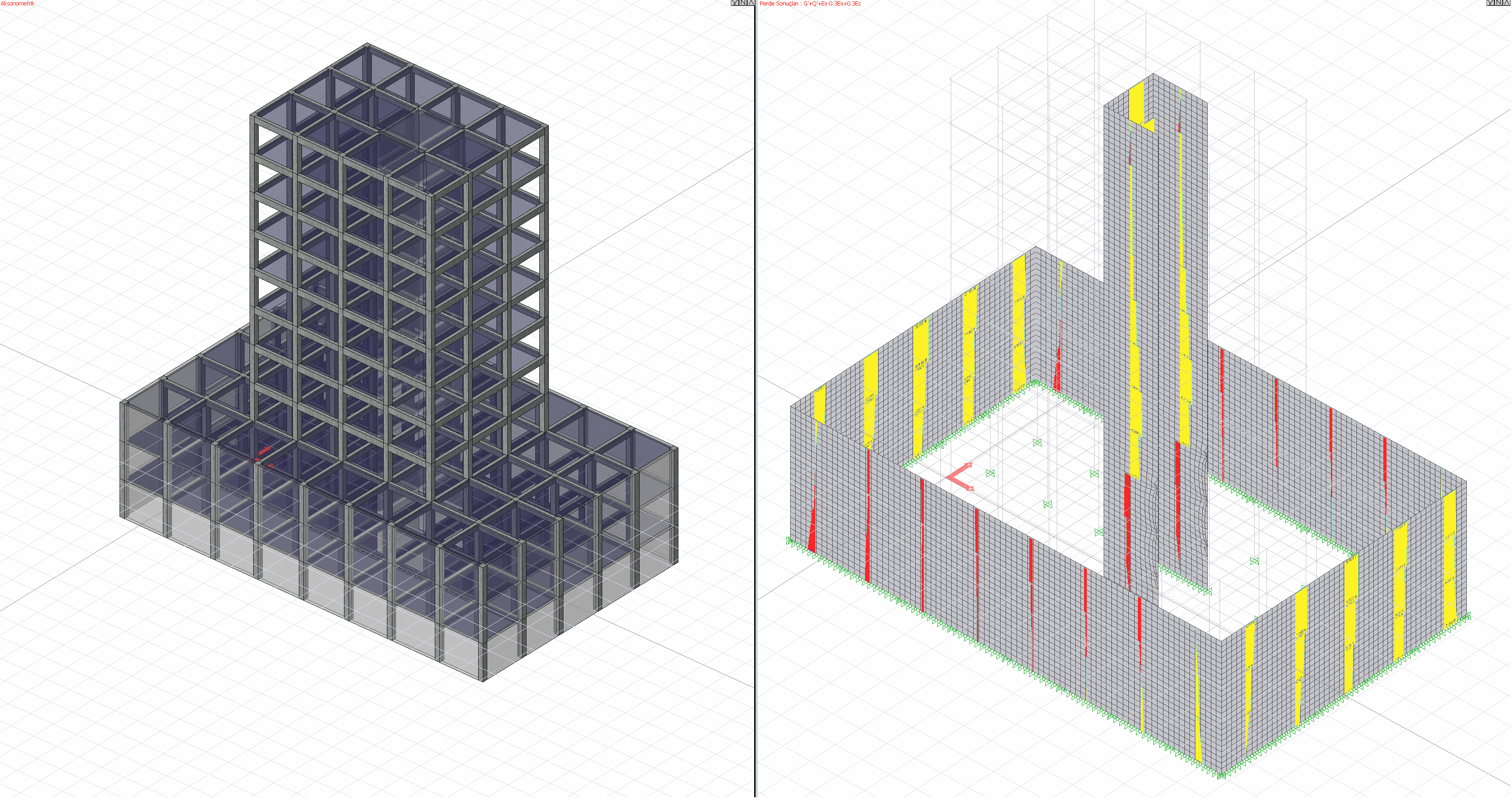
The stress distribution occurring in the transition floor of this structure is also shown below. As can be seen, the stresses increase in the sections where the floors are connected to the shearwalls. Although the structure does not have type 2 and 3 irregularities, the stress values may increase at certain points of the slabs. This situation arises only with the two-dimensional finite element solution.
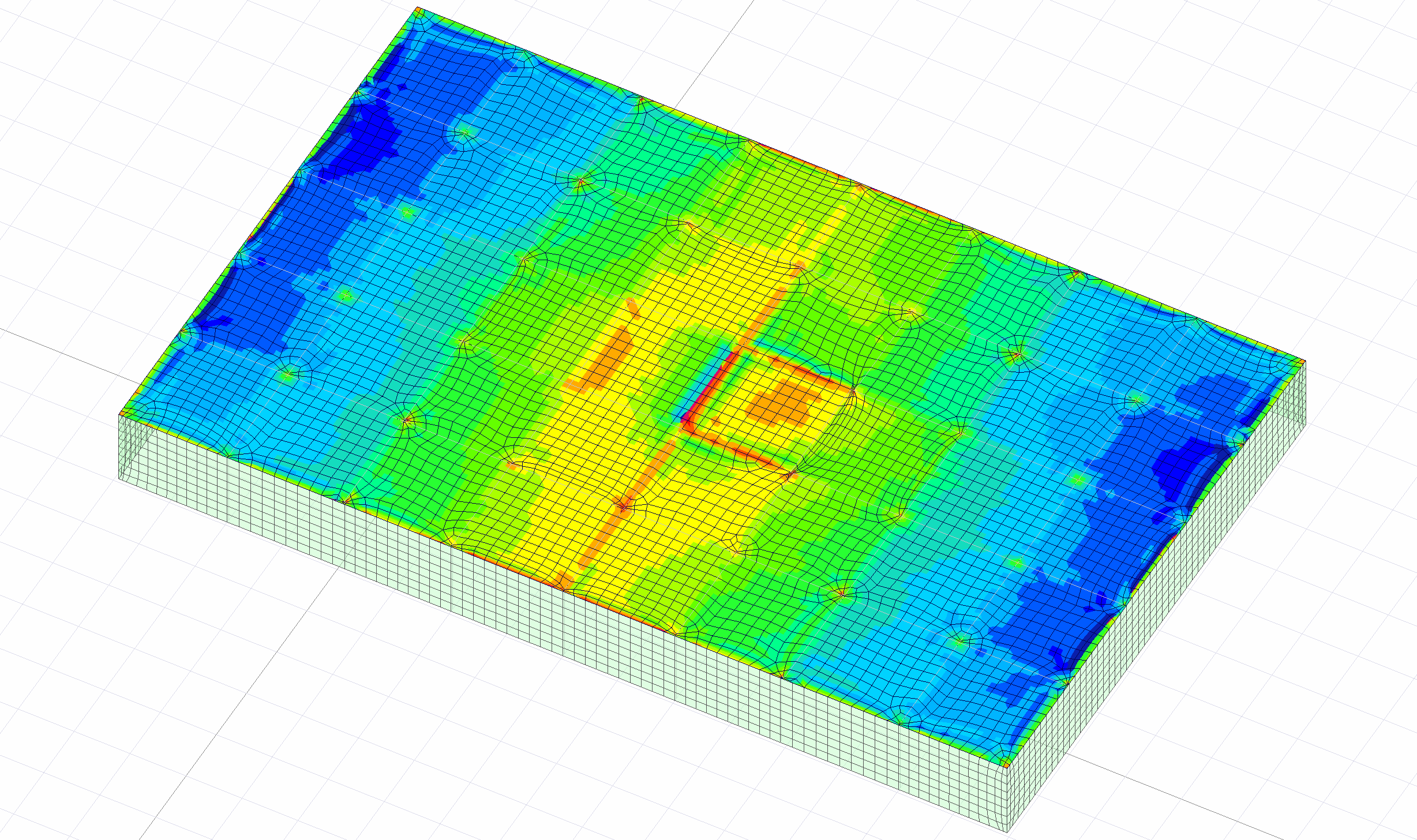
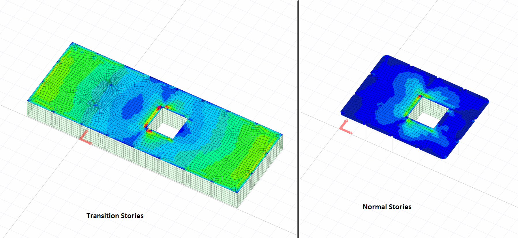
In the picture below, the transition layer and normal floor slab shell finite element results are compared with the color scale. As can be seen, due to the earthquake effect of normal floor coverings, there was only an increase in stress around the horizontal load-bearing system. However, the stress values in the transition layer are higher than the normal layer stress values. The stresses created by the loads transferred to the horizontal load bearing system in the transition storey floors are also relatively higher than the normal floor.
For the reasons explained above, transition story floors should be modeled with semi-rigid diaphragm acceptance. If the floors, that should be modeled as semi-rigid diaphragms, are made with the acceptance of rigid diaphragms, the increase of in-plane stresses due to the earthquake effect will not be taken into account.
It should be shown by calculations that the in-plane effects are safe to transfer to vertical bearing elements in floors analyzed with the acceptance of semi-rigid diaphragm.
Next Topic