
After the nonlinear thrust analysis is performed, the displacements and damage status are displayed in color by selecting the nonlinear thrust analysis combinations in the 3D visualization.
Location of Pushover Analysis Results
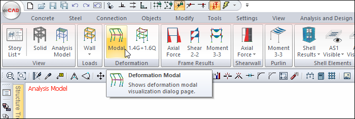
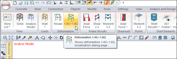
You can access the Deformation tab by clicking either Modal or 1.4G + 1.6Q commands under the Deformation heading under the Ribbon menu Structural Onspection tab .
You can also access the Deformation tab by clicking the Analysis Model command under the ribbon menu, Concrete tab, Structural Inspection heading .
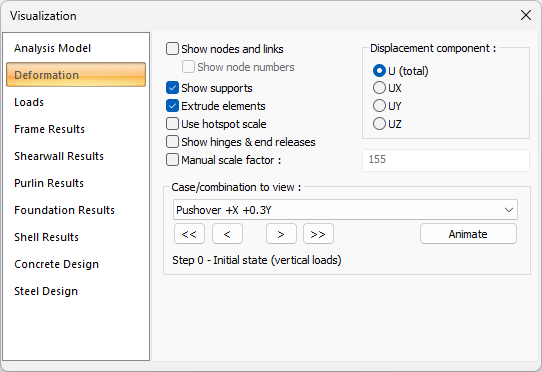
Visualization is provided by selecting one of the pushover combinations from the combination list under the deformation tab.
Pushover Analysis Examples
|
Sample screenshot with full body view checked 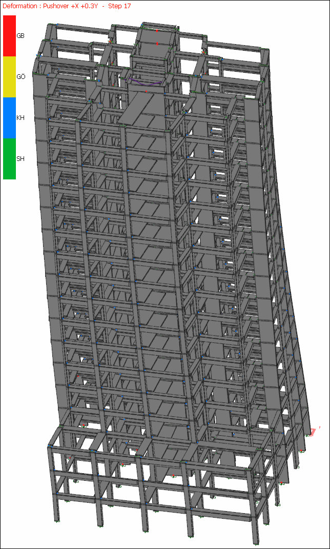
|
|
Full body display with cancel mark, sample screenshot as wireframe 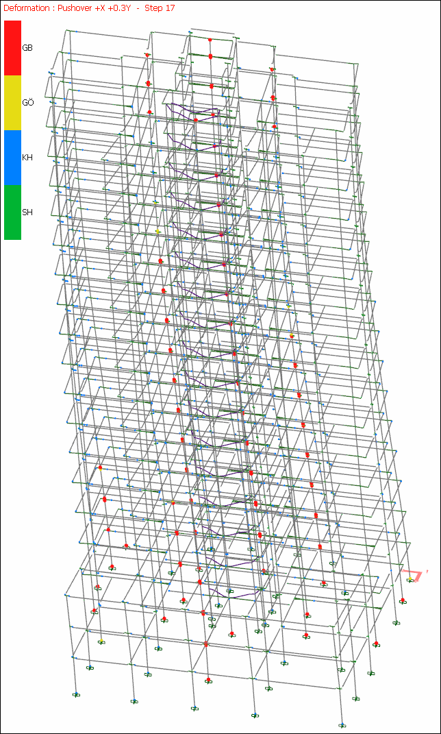
|
Hinge Colors and Meanings
|
Joints |
|
GB Collapse Level |
|
GÖ Collapse Prevention Level |
|
KH Life Safety Perfomance Level |
|
SH Immediate Occupancy Level |
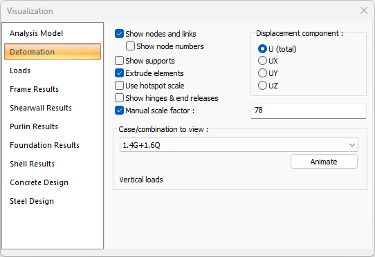
Deformation Tab
|
Specifications |
|---|
|
Show nodes and links If checked, all nodes created in element joints in the analysis model are shown as red points. |
|
Show node numbers Activates if show node numbers is checked. If checked, the names of all joints are also shown. |
|
Show supports If checked, the supports in the frame system are shown. |
|
Extrude elements If checked, the frame system is shown as solid (solid). If not checked, it is shown as a line (bar). |
|
Use hotspot scale It provides rapid examination of deformations by making color grading between dark red and yellow from less to more. |
|
Show element and releases If checked, the information of the elements with end freedom is displayed on the element. |
|
Manual scale factor If the option is not selected, the scale factor deemed appropriate by the program is applied for the deformations. If checked, the desired scale factor value can be entered manually in the box on the left. |
|
Case/combination to view 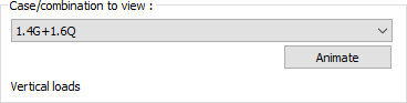
The combination row in the list is clicked on whichever load condition you want to examine. The animation can be viewed by clicking the play button. |
|
Displacement component to view 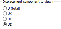
The displacements of the structure are shown if it is selected from the options U (total), UX (x direction), UY (y direction), UZ (z direction). |
Next Topic